- Design Concept
3.1 Site Context . 3.2 Building Form . 3.3 Interior Space . 3.4 Double Skin . 3.5 "Fish-mouth" . 3.6 Environmental Controls .
- Studies of Natural Ventilation
4.1 Wind Condition . 4.2 Building Aerodynamics . 4.3 Facades . 4.4 Reduction of Wind Pressures . 4.5 Natural Cross-Ventilation . 4.6 Influence of Window Opening . 4.7 Door Opening Forces . 4.8 Operating Restrictions in Natural Ventilation . 4.9 Summer Temperatures Inside the Facade .
| Created: 16 Aug 01 | Update: 23 Aug 2000 | By: Sam C M Hui (cmhui@hku.hk) |
| Location: | Essen, Germany |
| Client: | Hochtief AG |
| Occupier: | RWE AG |
| Date of Construction: | 1994-1996 |
| Architect: | Ingenhoven, Overdieck, Kahlen & Partner |
| Collaborators: | Achim Nagel, Klaus Frankenheim, Martin Slawic, Claudia de Bruyn, Regina Wuff |
|
Building type: |
Office building - administrative headquarters for the electric company |
| Building Envelope: | Josef Gartner and Co. |
|
No. of stories: |
31 |
| Gross Area: | 35,000m2 |
| Construction Cost: | £90 million |
| Climate Zone: | Temperate |
| Approx. Percentage of Gross Floor Naturally Ventilated: | 70% |
| Approx. Percentage of Net Floor Area Needing Artificial Lighting During Daylight Hours: | 30% |
| Fuel/Approx. % Use: | Mains electricity 99%; photovoltaics 1% |
2. Photo Gallery
|
|
|
|
|
|

|
Model Photo & Drawings |
| model.jpg 70Kb | site model.jpg 119Kb | concept1.jpg 143Kb | concept2.jpg 52Kb |


|
|
|
|
|
|
|
Exterior |
| DSCN0001.jpg 118Kb | RWETower.jpg 265Kb | eingang.jpg 366Kb | ||||
 |
 |
 |
 |
 |
 |
|
| buero.jpg 270Kb | DSCN0008.jpg 652Kb | DSCN0007.jpg 613Kb | DSCN0002.jpg 874Kb | DSCN0009.jpg 638Kb |

|
|
|
|
|
|
|
Interior |
| treppe1.jpg 497Kb | DSCN0003.jpg 100Kb | |||||
 |
 |
 |
 |
|||
| int5.jpg 67Kb | int6.jpg 92Kb | int7.jpg 84Kb | DSCN0006.jpg 401Kb |

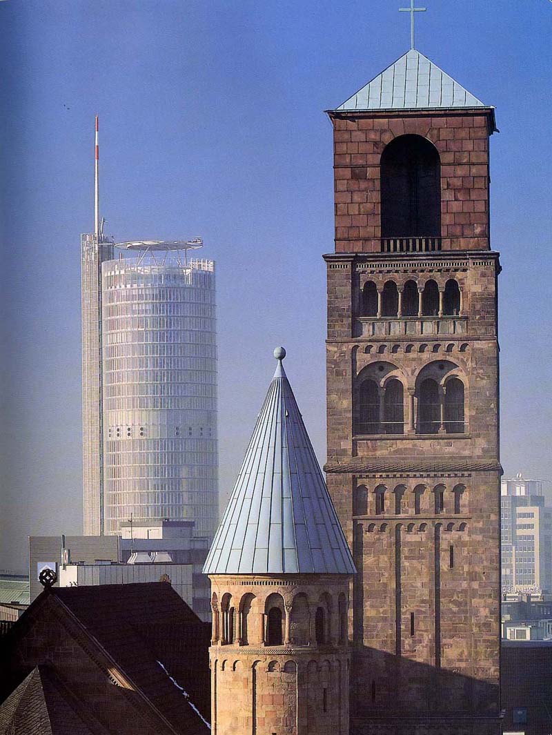
As is widely known, in Europe any new building is
required to blend in with the other buildings in a street.
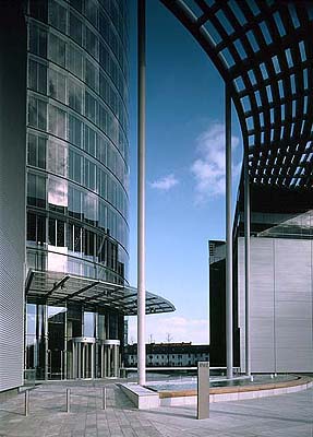
The RWE Tower has the main building set back from the street, along with
the pergola the height of which is aligned with the eaves of neighbouring
houses. There was still need to obtain the special sanction of the
municipal authorities to construct the skyscraper. As Achim Nagel, one of
the IOK architects, explained, churches dating back to ancient times were
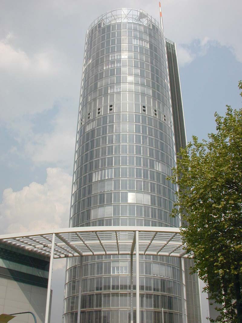
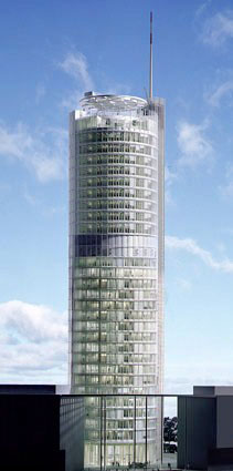
the only tall buildings. The 162m height of the tower, including an aerial
on the top, is the highest point in North-Rhine Westphalia, but does not
look isolated, when it is seen from anywhere in the city. Its abstract and
clear external appearance is essentially in harmony with the row of stores
and houses in the street.
When compared to other prismatic forms, the cylindrical shape is ideal in terms of the relationship between exterior surface and interior volume. It also optimizes aerodynamics, energy needs, surface distribution, and choice of prefabricated elements.
With the cylindrical shape, air speeds are twice the wind pressure, which eases vertical circulation of airflow and the diagonal ventilation in all stories.
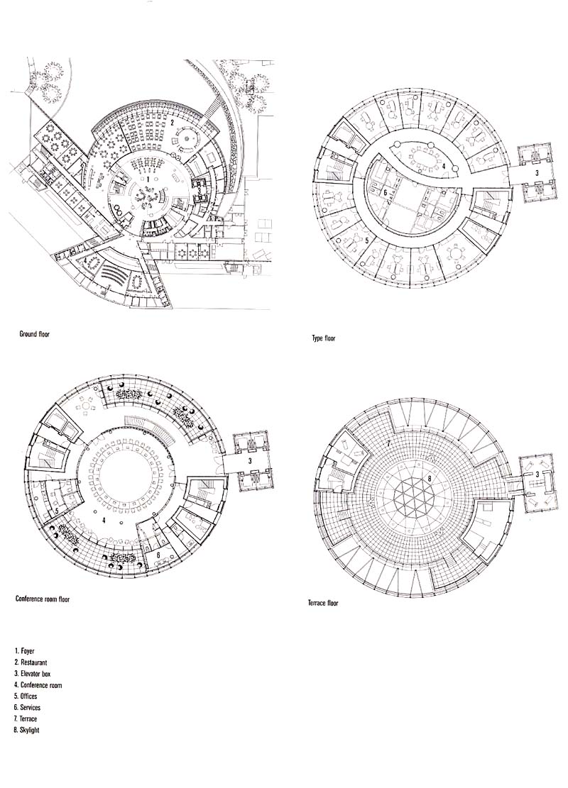
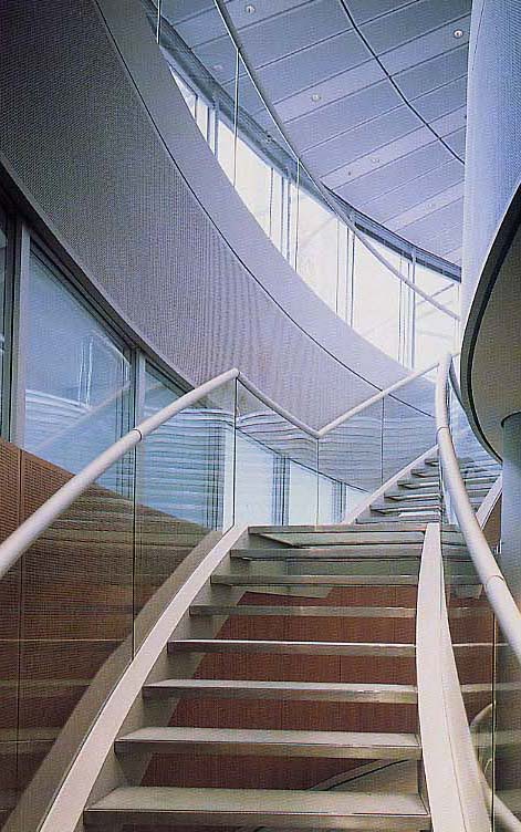
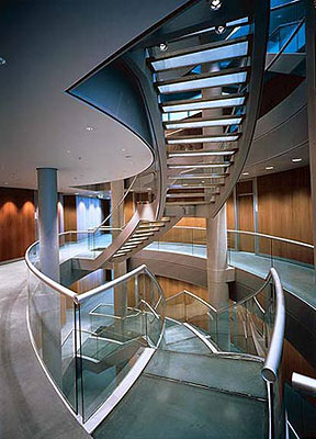
The architects chose to separate the vertical communication cores and group them into a svelte, attached column. This simplified the distribution of offices, making the most of the interior space. The office levels are configured around a nucleus; they subdivide into conference rooms, round hallways, and peripheral bands of offices and stairs that interconnect some of the levels. The outer glass skin allows natural light to reach the internal core.
Each floor has a theme:
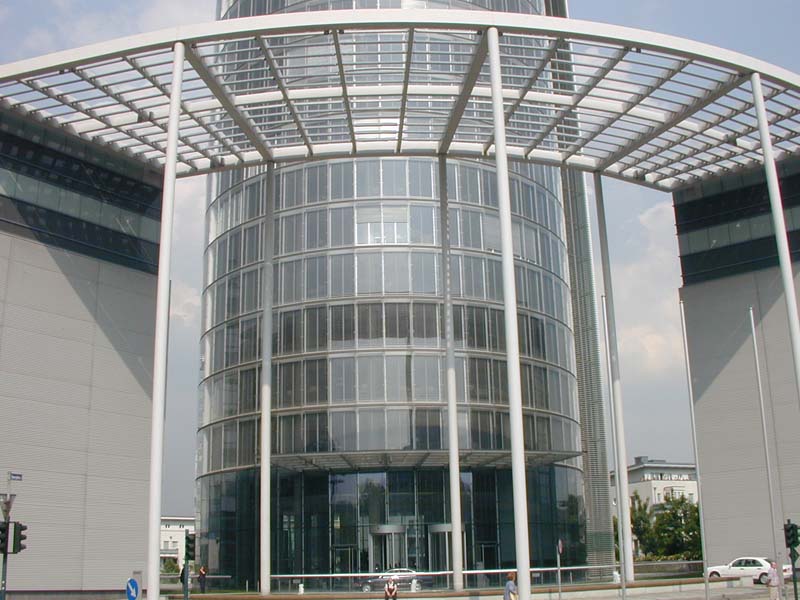
- Entrance Hall with Sense of Space
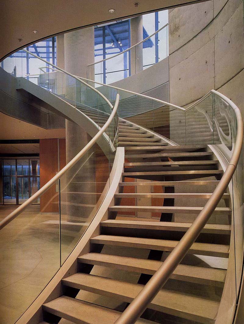
The elevator shafts are housed in a tower, detached from the main tower, so the ground floor has ample open space to share a continuity with the theater and the city park. On this level, the columns are a significant factor in the design, to indicate that the building is supported by them, whereas a sense of space is available at the same time. As with the columns, the walls are rough concrete, and the surface is coated with water paint for protection.
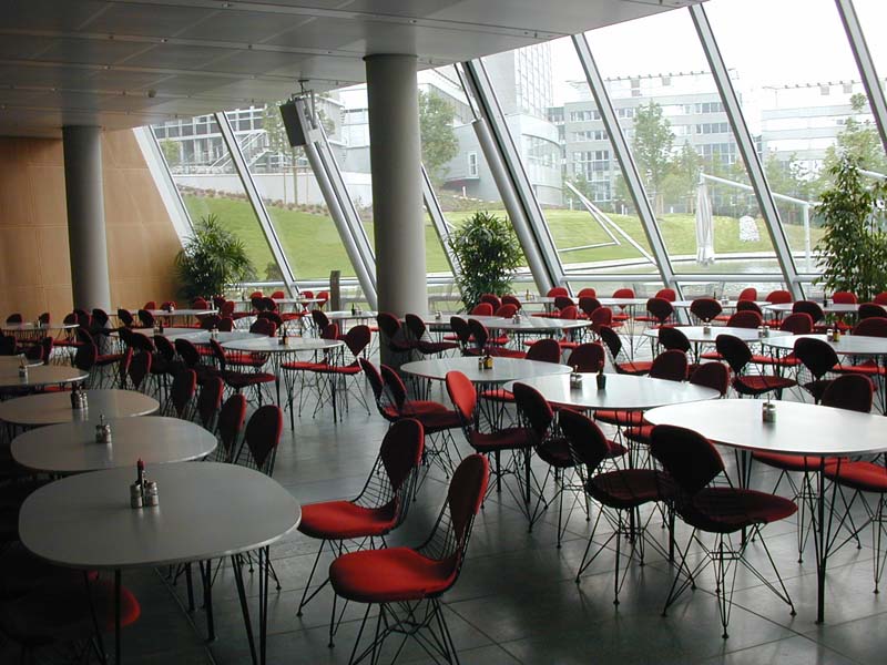
- The Basement Open to the Garden
The first basement (actually half-underground) with a total surface area of 600sqm has a staff restaurant and dining rooms, the facade of which is glazed from floor to ceiling, since the view of the garden in the site is regarded as important for relaxation. The glass of the facade was formed from the development of a truncated cone. Every part of it has a different size and shape. The staff restaurant has three glazed doors for access to the garden over the lake.
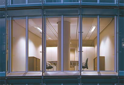
Nature-oriented Office Rooms - The 2nd-18th and 20-24th floors are for office rooms. Due to the relatively small cylindrical plan of 32m in diameter, every office room faces the exterior, so as to admit the outer light directly and enjoy the panoramic view.
- Transparent Elevators
Four ordinary elevator shafts are installed in an independent tower built along side of the main building. Owing to their outside location, people can easily find where they are.
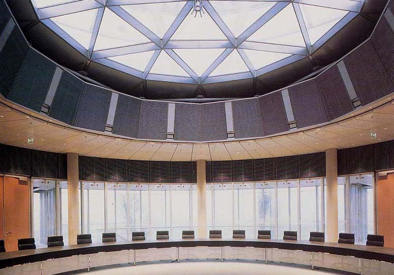
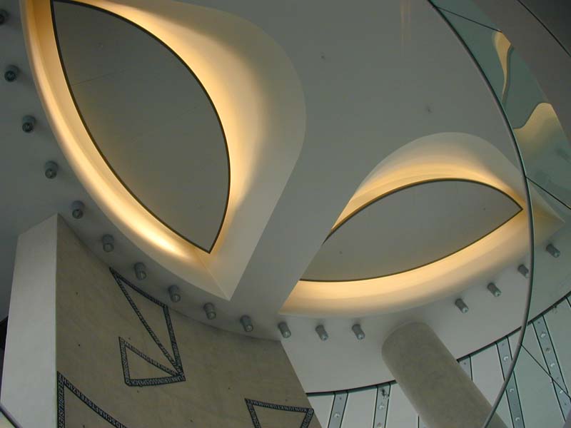
- Sunny Boardroom on the Top Floor
On the top floor, the 29th floor of the RWE Tower, there is a boardroom for gatherings of the RWE Group executives from around the world. The ceiling of the boardroom is fitted with a large toplight, and the sunlight from it is regulated by an electric curtain. Not only its facade, but also its partition panels are mostly made of glass, so as to enhance to view of the surrounding area.
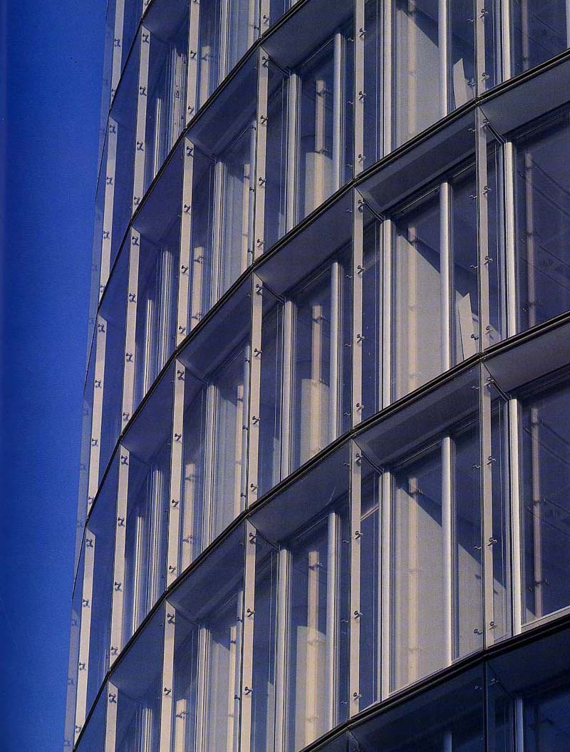
The main concern of the design of this 31-storey cylindrical tower is natural ventilation. This is achieved by its double-leaf facade, which is intended to provide good natural ventilation for perimeter office areas. The space inside the facade is supplied with outside air through a meandering arrangement of intake and exhaust louvres.
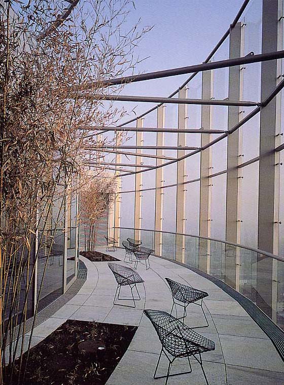
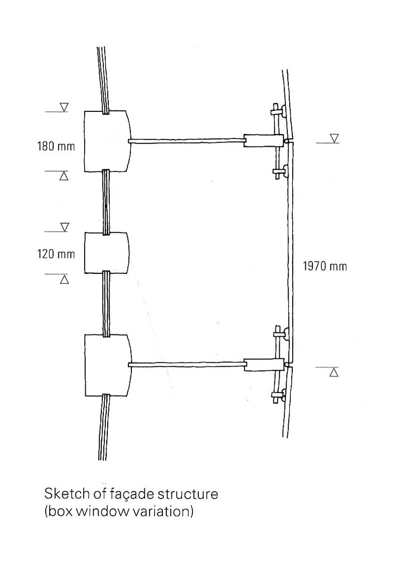
The double skin allows the RWE Tower to "breathe". It consists of an exterior sheet made of fixed glass panels - 2 x 3.6m modules that permit air circulation through corresponding slots, and an interior sheet with operable panels. A solar protection system is installed between both layers, which are 50cm apart. Strips, placed on the setting lines for the exterior facade modules, are perforated on the right side and solid on the left side, at the lower level. The disposition is reversed on the upper level, next to the roof, which guarantees a minimum diagonal of ventilation and prevents the return of recently evacuated air back into the spaces. The interior layer of the double skin is a conventional facade, insulated by collapsible panels that can be controlled manually.
- Sun shading & thermal storage
When the solar radiation is strong, the temperature inside the double-skin rises as in a greenhouse. However, owing to the air inlets and outlets fitted to the top and bottom of each story, the air convects so as to take the heat away. An experiment using a life-size model proved that the hotter the facade became relative to the surrounding air, the more remarkable the convection effect that was achieved, so as to carry out the sunshading function. Of course, the thermal storage effect becomes vital, when there is a need to warm the room as in the winter season.
- Natural Ventilation
The double skin allows natural ventilation in the tower. Even the upper workspaces can enjoy natural air control without having to fight wind gusts. Users can control their own environment.
The natural ventilation in a high-rise could give rise to the following fears: a very force power might be required to open the room doors; the wind might stream from the room to the corridor, blowing papers about; the wind might also make disturbing noises. Actually, natural ventilation may be restricted or influenced by such constructional parameters as:
- facade layout,
- ventilation slits or louvres,
- air-tightness of windows and doors,
- design of doors (revolving doors, opening and closing mechanisms).
After the investigation of these condition for cross-ventilation during the design stage (which will be discussed in section 4), the mentioned problems have been solved by the design specific. Namely, the power required to open the doors is some 20% less than that in a 7-8 story building with a conventional facade; the wind entering is regulated, so as not to blow papers about; the air inlets and outlets are designed not to make noise. During some 70% of the year, it is possible to live in the high-rise with the controlled natural ventilation, without artificial cooling or heating. Of course, as the inner facade can be freely opened up to 15cm, the individuals in the office rooms can let in the wind to satisfy their own requirements. Of course a system of mechanical ventilation is also installed, but it is operated at most twice an hour, whereas there is a need to ventilate 4-6 times hourly and to spend a lot of energy to cool or heat the air in more conventional buildings. By harnessing the natural ventilation, one can avoid sick-building syndrome which one is apt to get in full air-conditioned multi-story buildings.
When the weather is forbidding, temperature is managed by an air-conditioning system with a minimum capacity of air recycling.
|
|
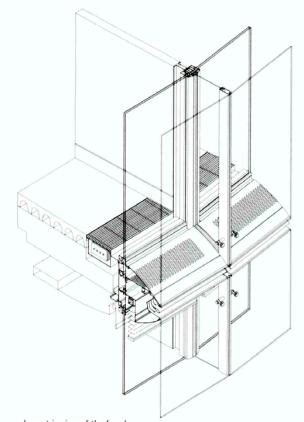
The parts that support the outer facade
as well as absorb or exhaust air are called "fish-mouths"
by the architects, which are responsible for both the intake and
outtake of air in the double-skin.
This is a pair of sashes, where one carries a "fish-mouth" with small holes on its upper part exclusively for intake, and another has a "fish- mouth" with small holes on its lower part exclusively for outtake, as indicated in the plan. Due to such a composition, the outside air from the intake "fish-mouth" is warmed inside the double-skin and diagonally ascends to be exhausted from the outtake "fish-mouth" at the neighboring sash. If both the "fish-mouths" had been laid out vertically, exhaust air would take the shortest path up to the floor above and enter it in the place of fresh environmental air. If this happened, air quality would decrease with every subsequent floor. Because of the stack effect in stairwells and the elevator shafts, special attention was paid to where certain air locks and vents should be placed throughout the building. Through extensive wind tunnel and computer modeling, a design consensus was reached. When absorbed, the air stream is adjusted to a suitable speed, by going through the "fish-mouth." It is made slower in case the wind velocity is too great, whereas it is made faster in case their is no enough wind. Of course, no rain enters through the "fish-mouth." The sensors fitted to the aperture inform of the aerial conditions. As mentioned above, the "fish-mouth" can also be used by raising its cover as a footplate for cleaning, and is effective in preventing fire from spreading to upper or lower levels. Also, its gently curved bottom side is formed to reflect sunlight moderately and to take in solar energy to the maximum extent. Incidentally, because the air conditions, including the wind velocity, vary according to the altitude, there is a difference in size between the "fish-mouths" above the 16th floor and those below it. As a matter of course, exhaustive studies were performed until the form of the "fish-mouth" was finally determined. |

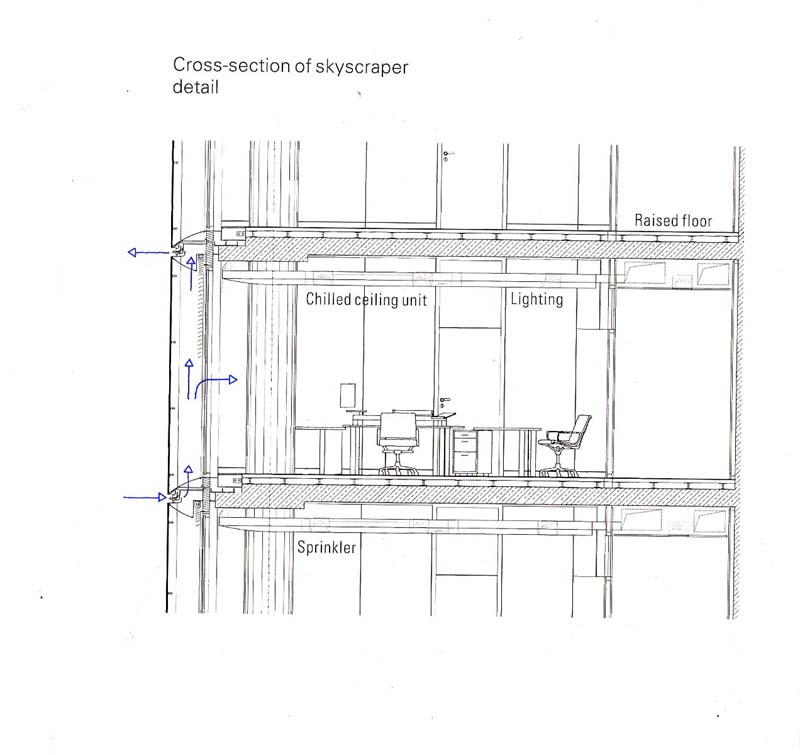
Environmental conditions are managed by Building Management Systems (BMS) technology, with a single control panel in every room enabling light, temperature, facade and sun protection to be adjusted to individual requirements. Integrated ceiling elements set into the concrete soffits are also multifunctional, incorporating low-energy lighting and a water-flushed pipework system for cooling, as well as smoke alarms and sprinkler systems.
4. Studies of Natural Ventilation
|
|
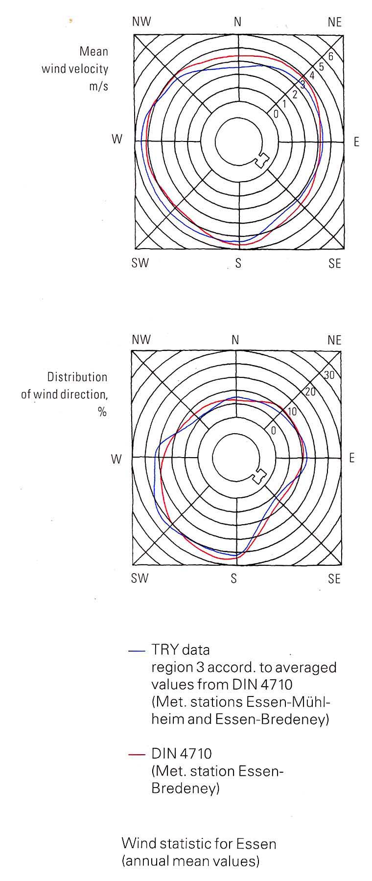
Wind velocities are measured at the local weather station. Winds are predominantly from the south, the south west, and the west, with a mean wind velocity (from KIN 4710) of 4.0m/s. Due to the difference in height, wind profiles near the skyscraper & the meteorological conditions at several levels were further investigated.
|
|
|
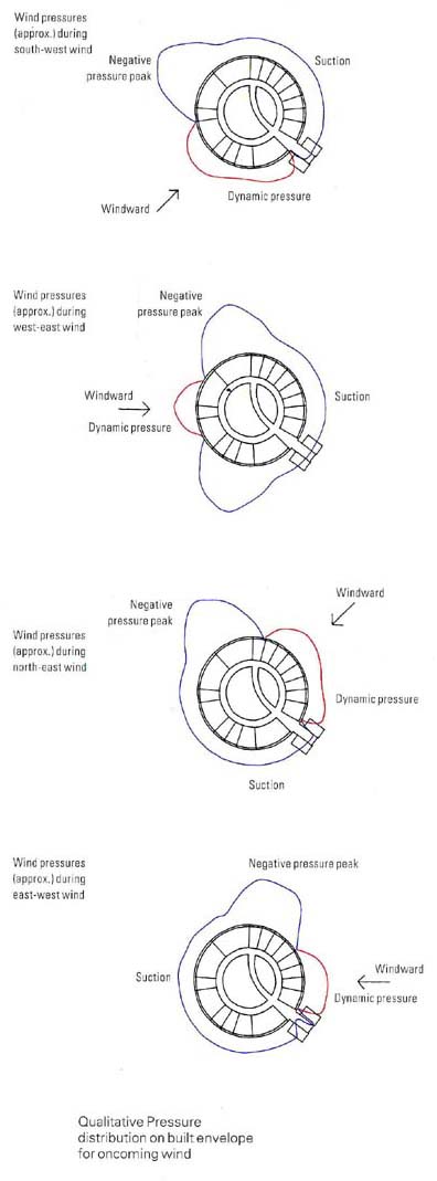
Wind pressure coefficients were determined in a wind tunnel study for the stimulation. The qualitative course of pressure distribution on the cylindrical exterior from 4 directions was recorded in the figure on the left. The result of the wind tunnel test showed a marked pressure differences (+1.0 to -2.3), which would lead to an intensive cross-ventilation. |
|
|
The double skin facade is intended to maintain floor by floor separation with the help of horizontally arranged dividers. To prevent exhaust-air influx into the lower floors, the exhaust louvre is diagonal in relation to the intake louvre. With regard to the lateral dividers, the following variations were studied:
|
|
|
4.4 Reduction of Wind Pressures
|
|
Without vertical dividers, the wind pressure can be partially reduced through free air movement in the direction of the building circumference in t he double facade cavity. The pressures inside the perimeter facade are essentially defined by the relation of the flow resistances for the ventilation louvres and by the facade cross-ventilation. From the resulting figures, it is clear that the wind pressure differences acting in the cavity can be reduced by 50% during easterly wind in comparison with results given for the box window variation. |

|
|
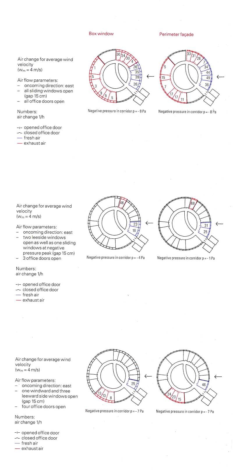
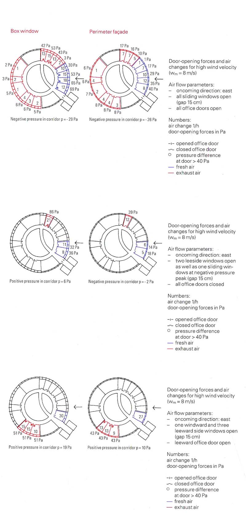
The final simulation reproduces natural cross-ventilation, based on the pressure coefficients resulting from the wind-tunnel test. To simulate Cross-ventilation, observations were made of the following opening situations for easterly wind at an average velocity of 4m/s:
The result of comparing the air-change behaviour in the opening situations under observation for the perimeter facade (double-leaf) and the box window variation is recorded in the figure on the left. (The numbers on the diagrams represent hourly air-change rates due to natural cross-ventilation).
|
4.6 Influence of Window Opening
Occupants can lessen the opened gap of the sliding door to manipulate the cross-ventilation in the room and to adjust it to their comfort level. It has been observed that a reduction of air change is possible when the gap is reduced for both the perimeter facade with two sectors and for box-type windows. The reduction is stronger in the former case, because of the pressure balance created by the facade cavity.
|
|
When office doors are kept closed, cross-ventilation is very limited. However, the wind pressures on the outer envelope of the building also affect the offices, exerting pressure on the office doors and hence increasing door-opening forces. The following criteria were used to evaluate the forces acting upon doors:
Furthermore, the evaluation was based on the assumption that no door closers would be used. When doors are equipped with closers, the opening forces would be exponentially increased by the door-closing force, whenever the operative directions of pressure force and door closers coincide.
|
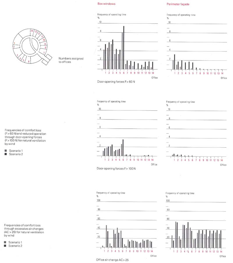
4.8 Operating Restrictions in Natural Ventilation
|
|
Prediction can be
made on how frequently natural ventilation may be restricted because
of increased door-opening forces or draughts in a typical year. In
the 1st scenario, windows and office doors can be opened in the
observed office space and in all other offices; and in the other,
doors and windows can be opened only in the office space observed
and in one other office.
|
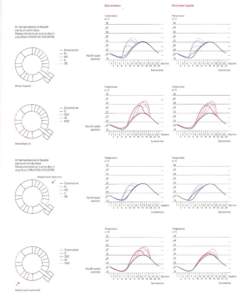
4.9 Summer Temperatures Inside the Facade
|
|
The
fluctuation of summer temperatures inside the double-leaf facade is
important in relation to window ventilation and the transfer heat
rate of the offices. In the simulation, an automatic shading device
was installed which closes when the solar incidence reaches 250 W/m2.
|
|
|
|
|
|
|


5. References
- The Technology of Ecologi8cal Building, Basic Principles and Measures, Examples and Ideas, p110-121, written by Klaus Daniels, published by Birkhauser Verlag, Basel, Boston, Berlin
- Ecological architecture, Bioclimatic trends and Landscape Architecture in the Year 2001, p118-127, edited by Aurora Cuito, published by LOFT publications, Barcelona, Spain
- Architecture and the Environment, Bioclimatic Building Design, p216-219, written by David Lloyd Jones, published by Laurence King Publishing, London
- http://www.nsg.co.jp/spm/sm81~90/sm86_contents/sm86_e_index.html
- http://www.rwe.com/eng/1.8_RWE_Konzern/Turm/Index1.html
- http://naturalvent.mit.edu/Europe/rwe.htm
| Case Study Index |