 |

| Case Study Index |
|
|
| Case Study Index |
|
| 1. Basic Data | ||||||||||||||||||||
|
| 3. Building Services Design | |
|
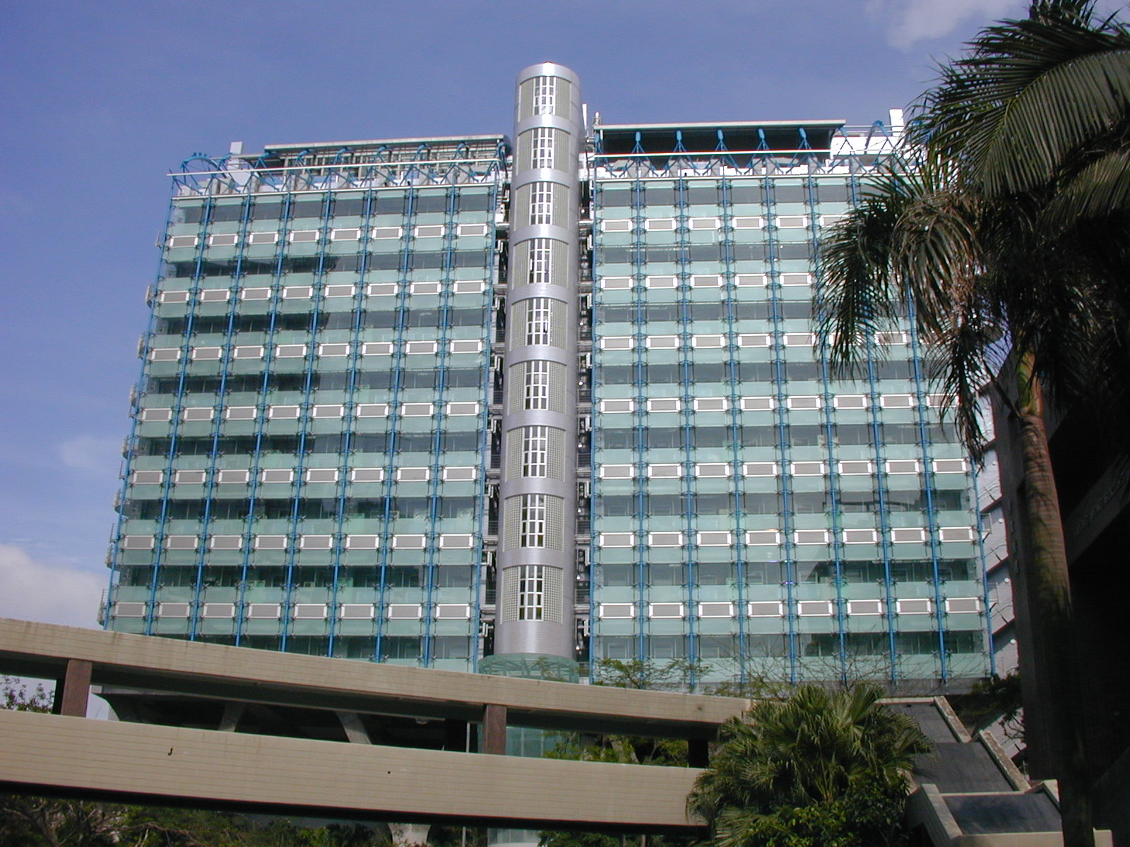
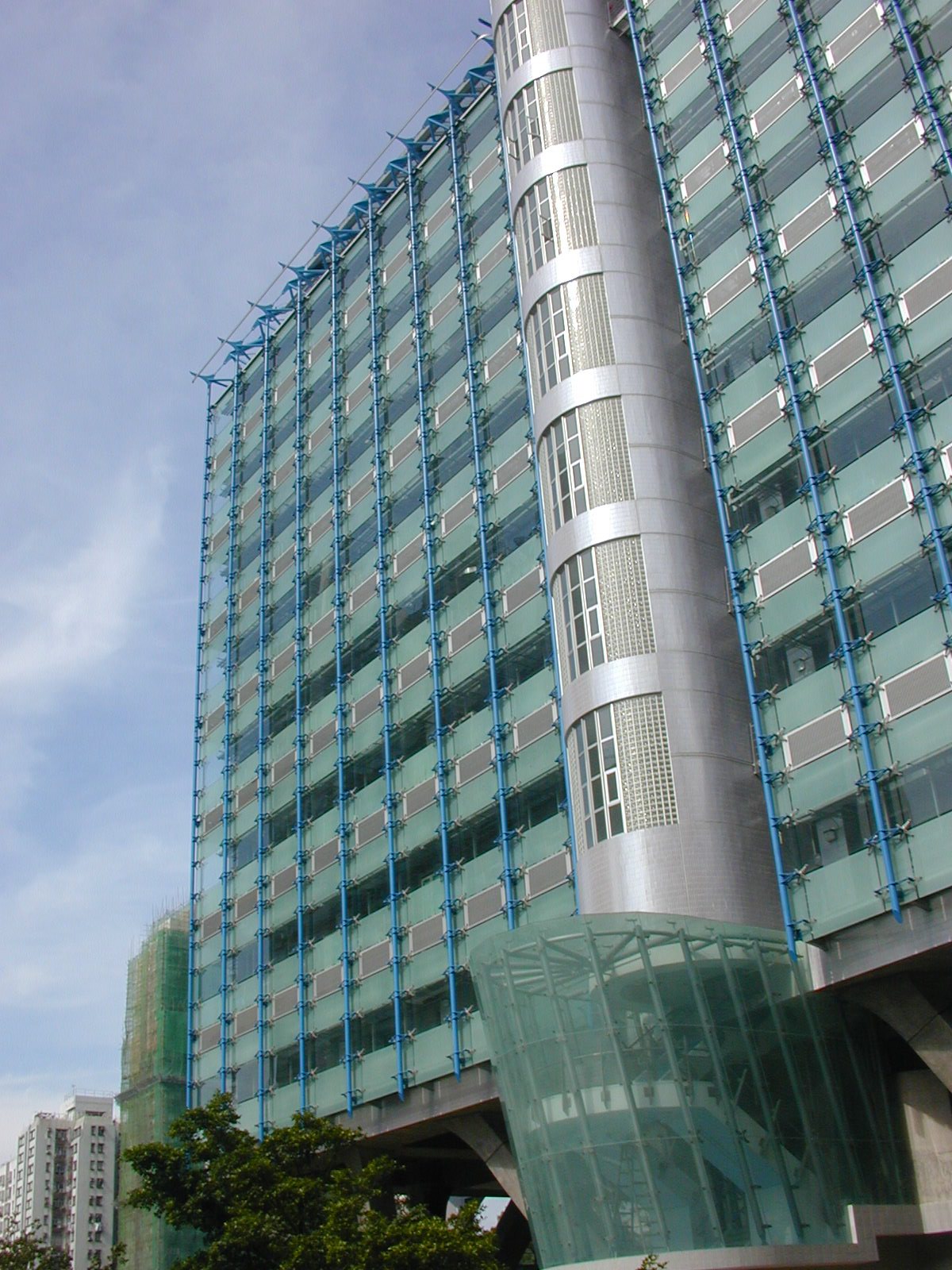
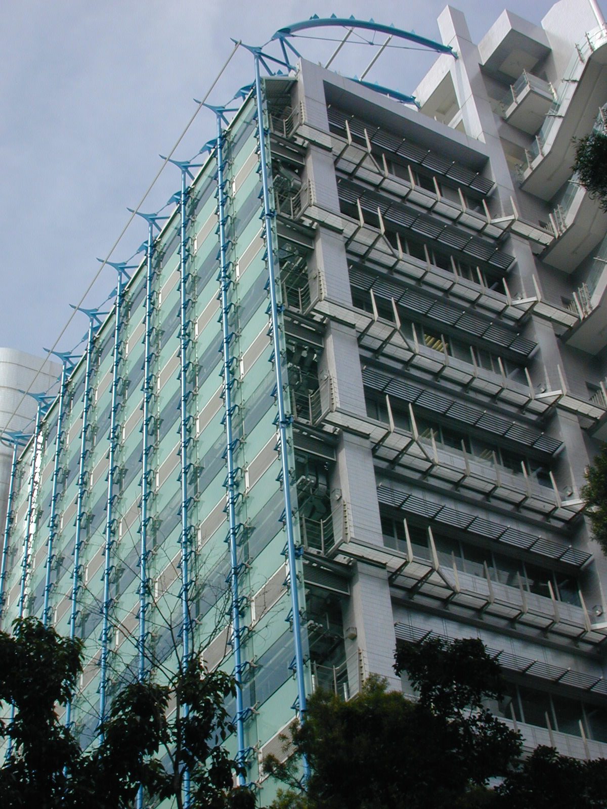
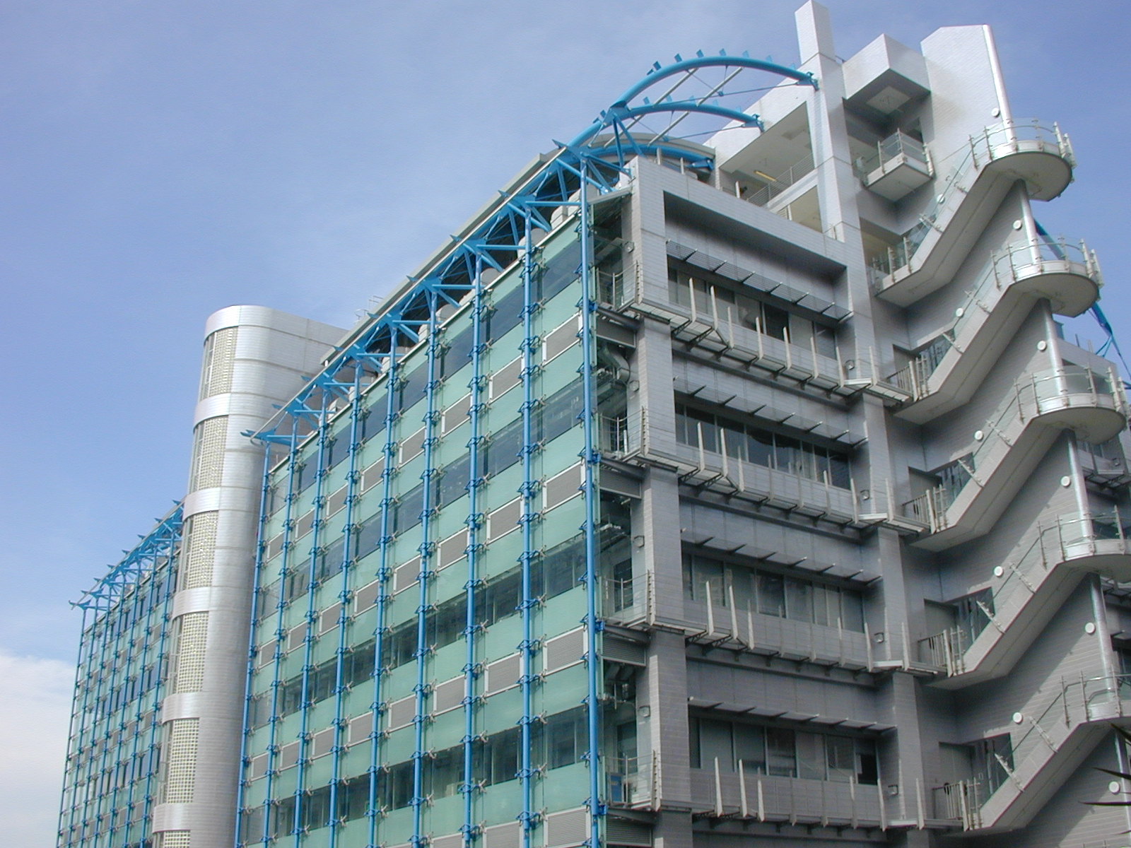
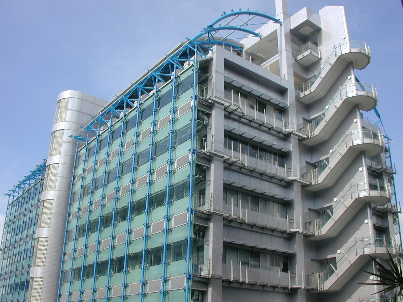
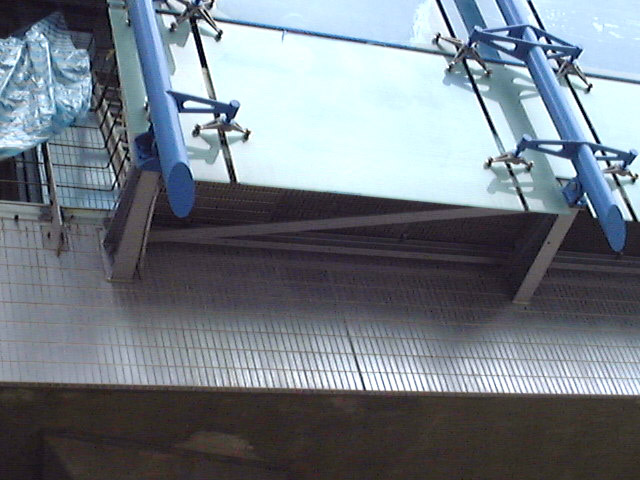
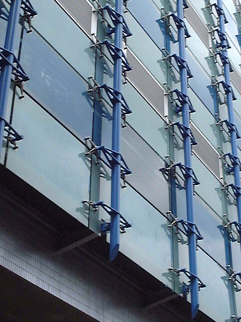
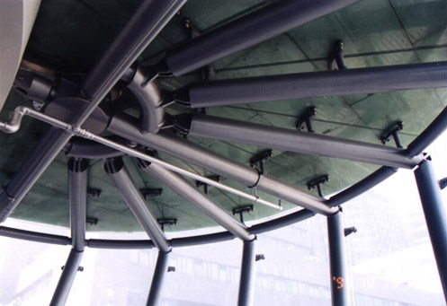
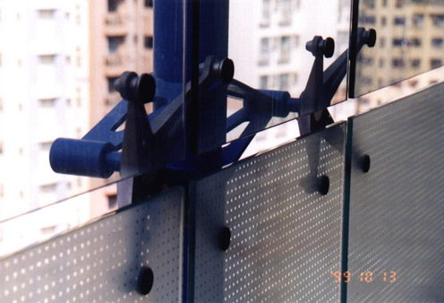
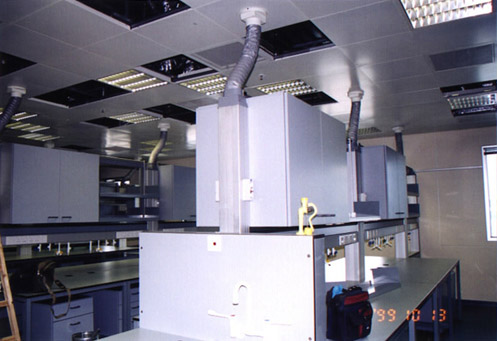
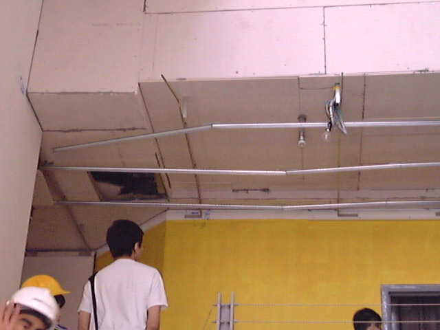
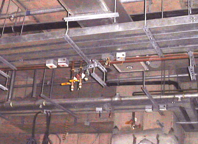
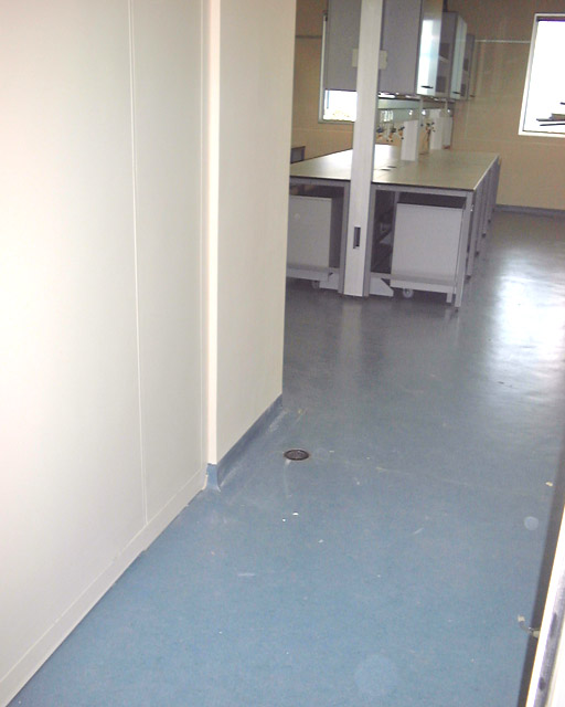
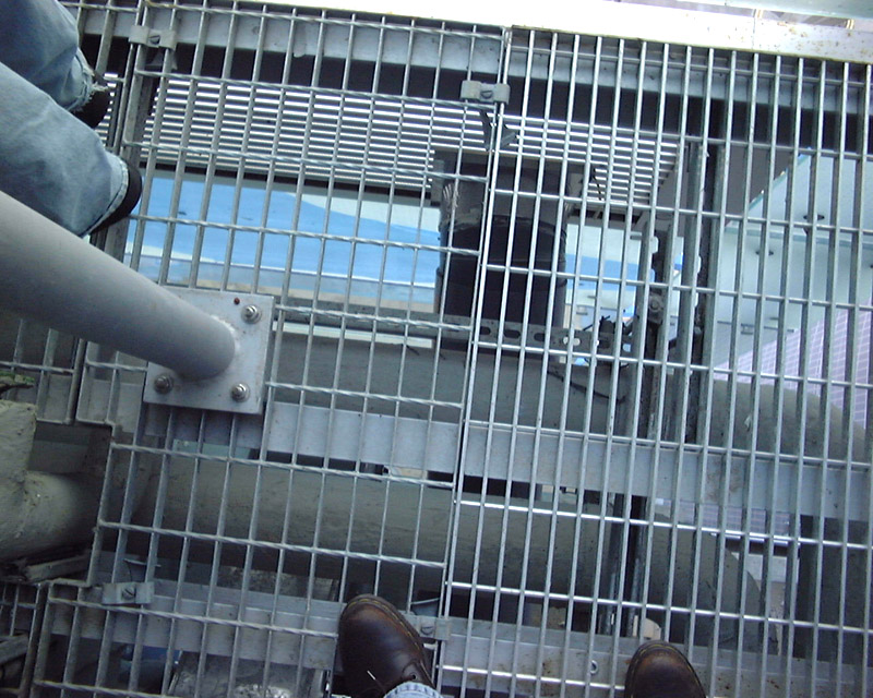
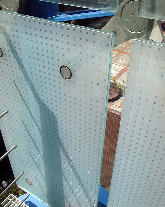
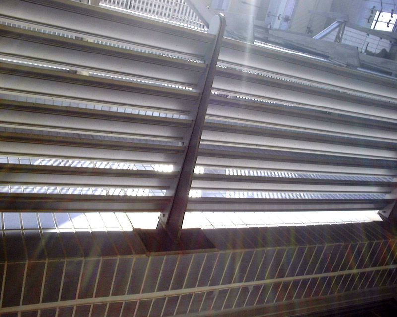
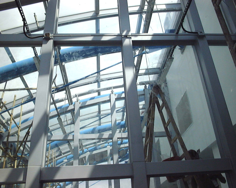
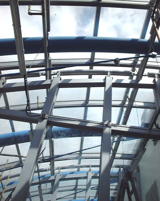
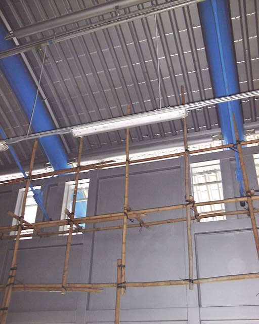
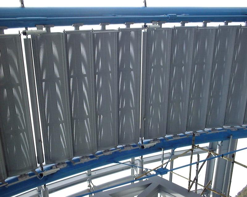
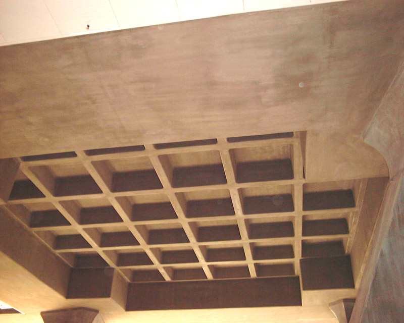
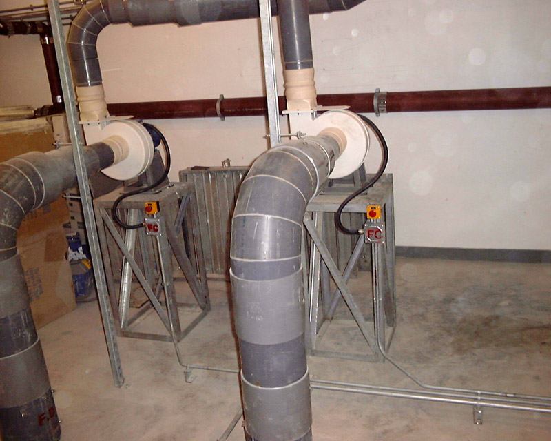
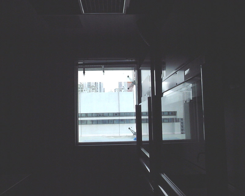
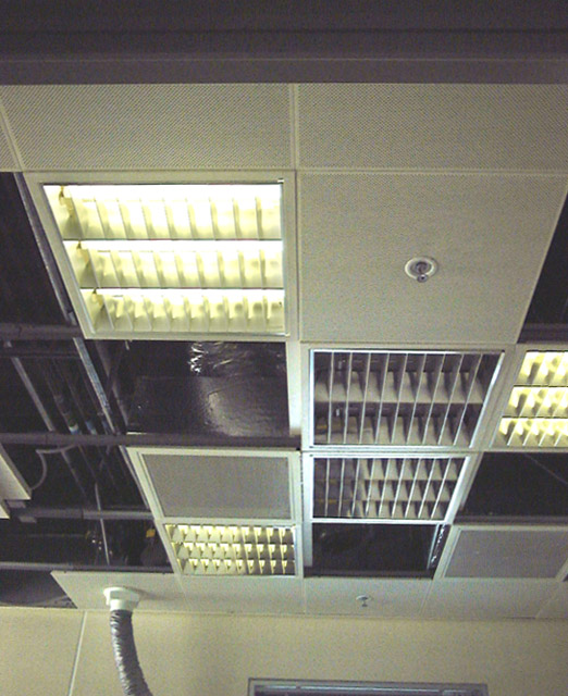
3.1 System Design Concepts Between the Double Skin The space between the double skin is not only used to accommodate the building services, but also used as an external buffer zone between the two layers of glazing, which acts as a stack that channels hot air upwards for discharge into the air, thus reducing the building's solar heat gain. An open metal grille installed at each floor allows free air circulation while serving as walkways for maintenance access. Heat gain is further reduced by locating heat emitting equipment in the external services zone outside the building, where they release their heat into the void rather than the interior. The design means that the building's air-conditioning system is used only to cool the space and not to overcome solar heat gain, thus dramatically improving the system's energy efficiency. By locating heat-emitting equipment in the external services zone and using an external glazed wall as a sunshading device, without taking into account various other energy-efficient and environmentally-friendly design features in the building, the architect estimated that savings of 53,360 kWh of energy per year, or 2.67 million kWh over 50 years, can be achieved. Carbon dioxide emission is expected to be cut by 37.6 tonnes per year or 1.88 million tonnes over 50 years. Ceiling The suites inside the building are subdivided into 600 basic units, but eh configuration is entirely flexible. All services are routed through the ceiling, which consists of a 3m by 3m ceiling grid containing all necessary services for laboratory functions, including compressed air, gases, electricity and telephone outlets. Services are routed into the 1.5 m deep ceiling void on each floor from the services spine. Flexible connectors distributed according to the 3 m grid allow all the services needed to be hooked up easily for instant "plug-and-play". Drainage provisions in the floor are also provided according to the 3 m grid. With ease of maintenance in mind the engineer designed a vacuum drainage system which sucks all drained material to a temporary store in the ceiling before final removal via ducting connected to the service core. Fume Cupboards The building is equipped with two types of fume cupboards: one which extracts hazardous fumes directly through the roof ; and a recirculatory fume cupboard for non-hazardous vapour. The latter kind is a particularly green feature of the building, which
only became commercially available recently. Developed by the British Atomic
Research Authority, the fume cupboards utilise vortex fume scrubbing technology
which, together with built-in carbon filtration, make them recirculatory,
thus cutting down on the air-conditioning load of the building. Since they
are moveable, these fume cupboards also contribute to the layout flexibility
of the laboratories. As they do not require a fixed rooftop scrubber and
extractor, a whole floor of plant space was freed up, which allowed the
architect to produce additional space to accommodate the later added Institute
of Molecular Biology. The re-designed roof also accommodates greenhouses
and an aquarium.
3.2 Building Services Drawings
MVAC
Fire Services
Plumbing & Drainage
Electrical Services
Other Utility Services
Combined Services Layouts
Laboratory Areas
Facade Detail |
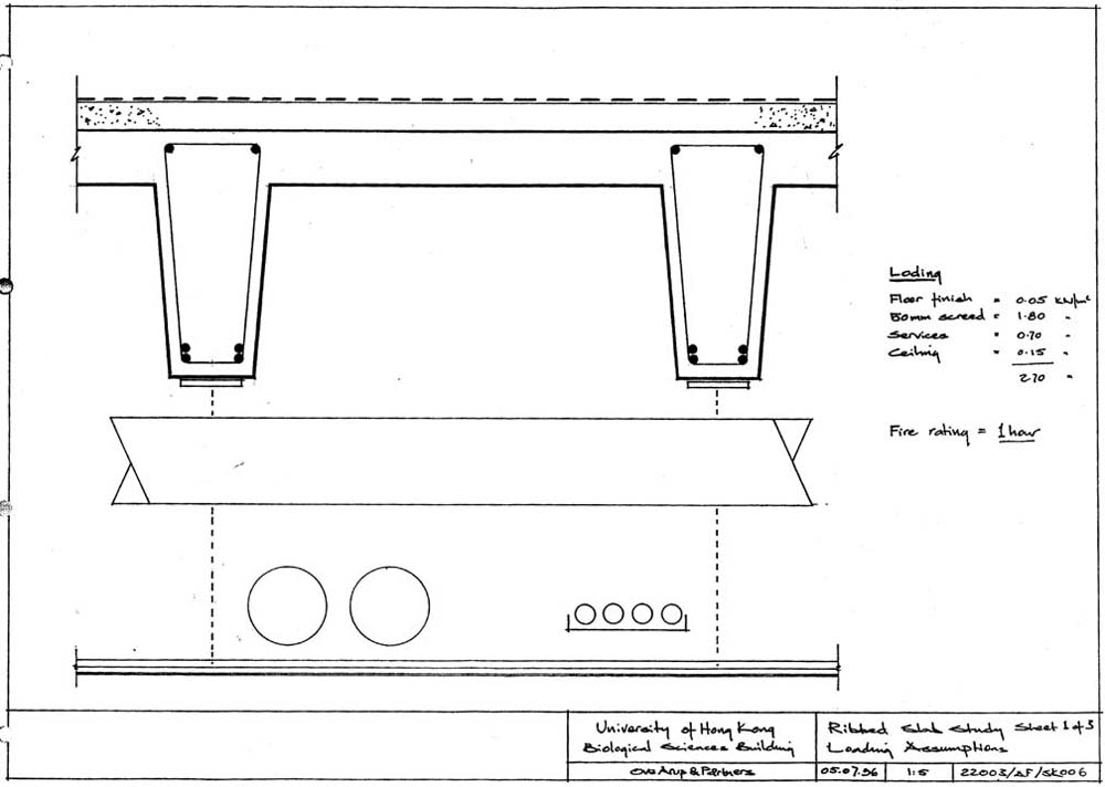
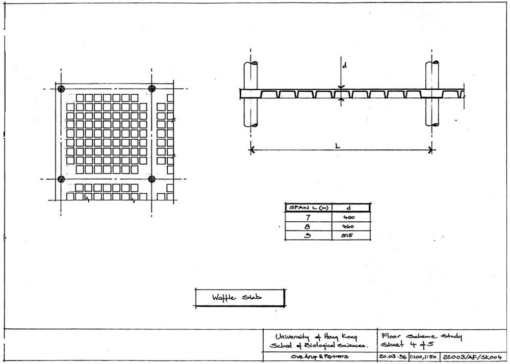
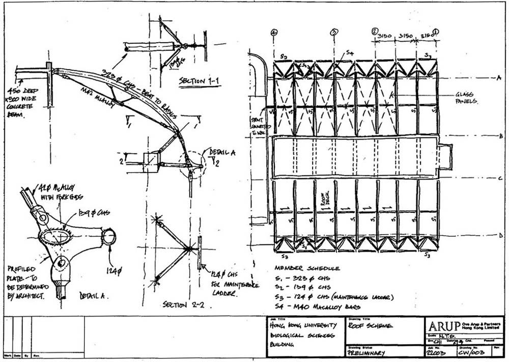
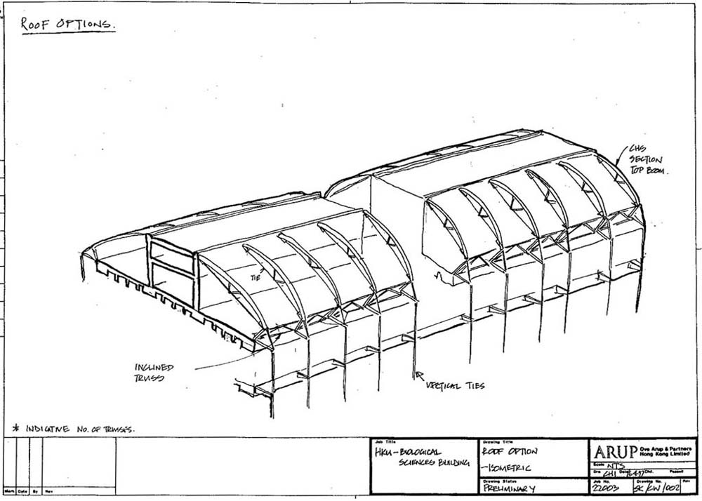
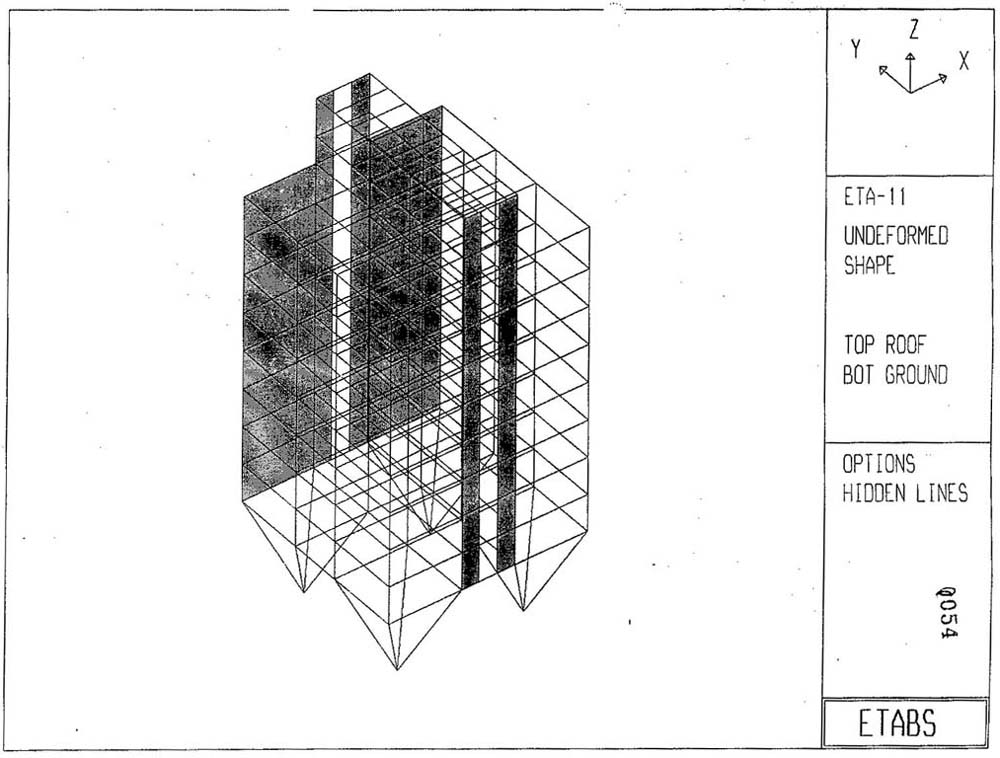
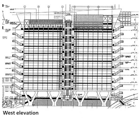
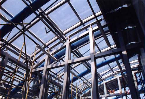
| 4. Structural Design | |||||||||||||
(* Extracted from a presentation by the structural engineering designer.)
Wind Loading
|
| 5. Photo Galleries | ||||||||||||||||||||||||||||||||||||||||||||||||||||||||||||||||||||||||||||||||||||
|
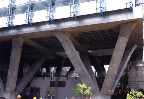
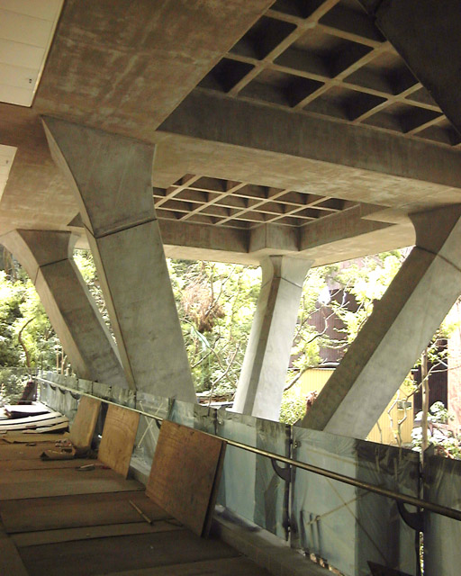
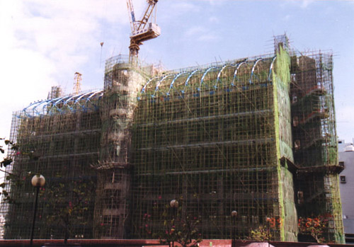
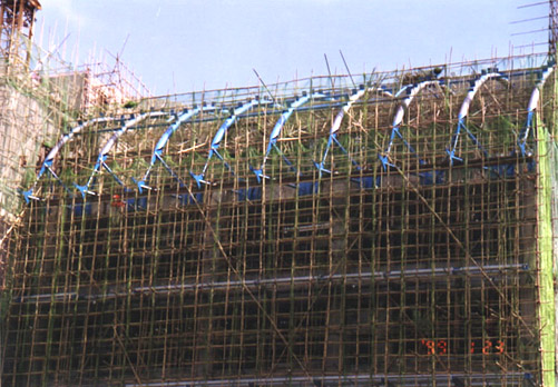
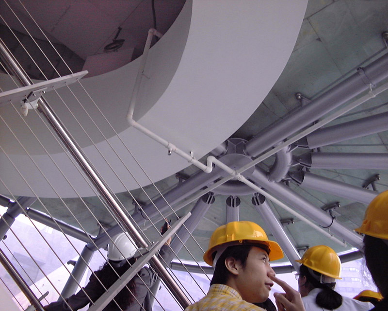
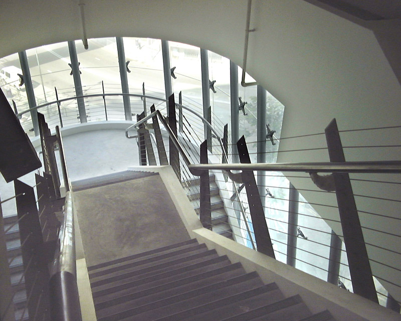
5.1 From Our Study Design Models and Concepts:
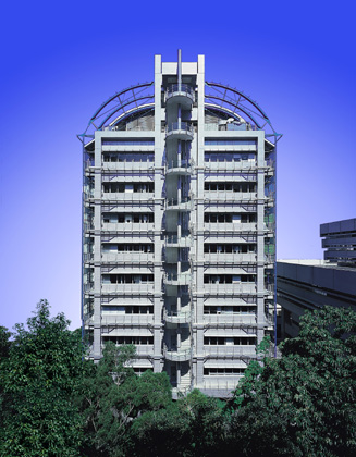
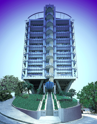
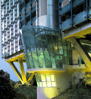
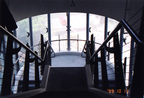
Exterior:
Interior:
|
| 6. References and Links |
| References Links
|
| Acknowledgements |
|
Sincere thanks are expressed to the following persons for providing us the project information.
|