| |
|
1. Introduction
The Tokyo Electric Power Company (TEPCO) built its new research and
development centre in order to integrate its four existing research installations
into one site. During the design and planning phase TEPCO concentrated
on rationalising energy use as far as possible at an electric utility's
R&D facility, whilst maintaining a comfortable indoor working environment
suitable for creative activity. Work on the new site was completed in September
1994.
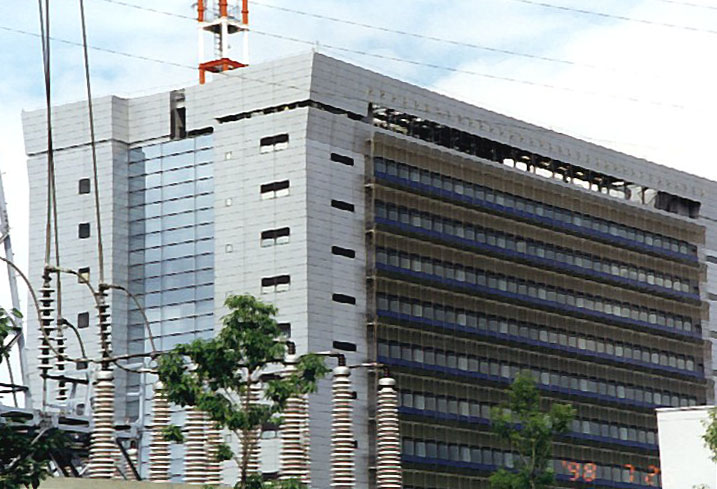
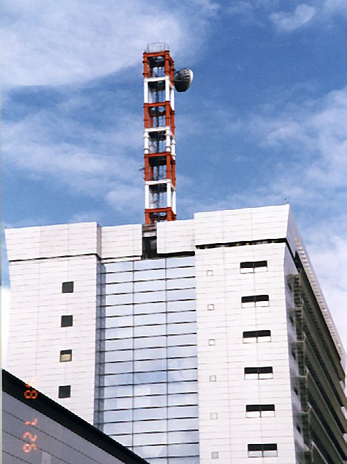
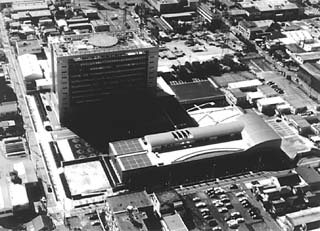
| Photo: Overall view of the R&D Centre
(seen from the north). |
 |
|
The centre comprises two main buildings. The research building (11 stories
above ground and one below, with a total floor area of 27,360 m2)
lies at the centre of the site (around 46,000 m2), with a welfare/conference
building (three stories above ground and one below, around 9,911 m2)
on the northern border. An entrance lobby (1,121 m2) connects
the two buildings.
A typical floor of the research building is 64 m long in an east-west
direction and 28.8 m wide in a north-south direction. To minimise the heat
load, the windows are arranged on the north- and south-facing walls. The
east and west sides of the building form the core sections, where machine/electric
rooms and common facilities, such as lifts and lavatories, are located.
The rectangular working space (51.2 m by 28.8 m) is divided into a northern
laboratory area and a southern open plan study room without partition walls,
where booths separated by low partitions provide privacy for each researcher.
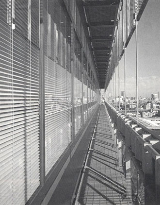
The outside balconies on the north and south sides provide emergency escape
routes.
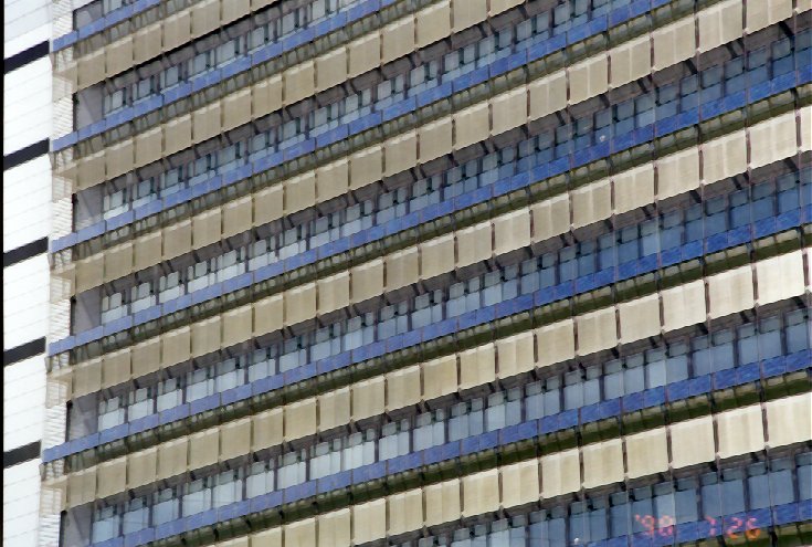
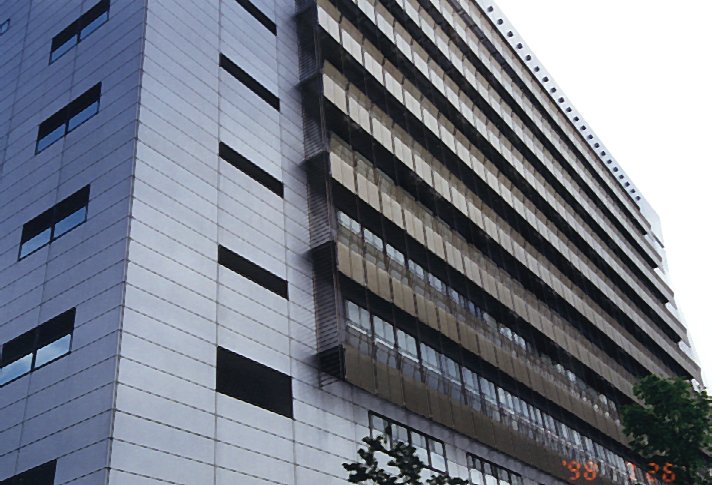
2. Architectural Features
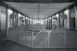
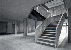
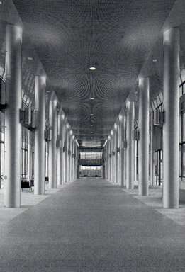
2.1 Photo Gallery
3. Energy Saving Design
(a) Control of Heat and Light in the Research
Building
To deal properly with the demands for both heat and light, it is essential
that offices are shaded appropriately against insolation. However, it is
also possible to significantly reduce the energy consumption for lighting,
and thus the cooling load caused by lighting, by using incoming sunlight
as a light source and controlling artificial lighting in accordance with
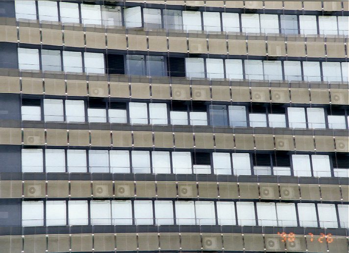
incoming daylight levels. In order to balance these needs, the south side
of the research building was fitted with ventilation windows with integral
automatic control blinds. A lighting control system was also installed,
which was capable of continuously dimming artificial lighting near the
windows over a wide dimming range (Figure 1).
|
Figure 1: Ventilation window and daylight-compensation lighting control
system (south side). |
|
(b) Ventilation Window System
The ventilation window is a double window with an integral venetian
blind between the two panes. Indoor air passing between the panes cools
the slats of the blind and removes the solar heat. This air then exits
through an outlet at the top of the window (Figure 1). In this way, the
window reduces the solar heat gain and the overall heat transfer coefficient
to between 1/3 and 1/2 that of ordinary windows. The ventilation window
thus not only considerably reduces the cooling load caused by excessive
solar radiation, but also eliminates the need for perimeter air-conditioning
units.
In order to reduce the perimeter cooling/heating load , the room air
flows upwards through the panes, and is exhausted outdoors as ventilation.
Effects of the system are as follows:
-
The passing air picks up solar heat which warms the blinds.
-
The temperature difference between the passing air and the room air narrows,
and overall heat transfer is reduced.
-
As the surface temperature of the inner pane is close to the room temperature,
people in the room feel more satisfied from the viewpoint of personal thermal
comfort.
To make the thermal insulation and shielding intended for the purpose of
energy-saving compatible with see-through visibility that enhances the
esthetical expression, heat mirror glass composed of laminated double glass
with a special film membrane inserted between two glass sheets are used
for the east and west glass curtain walls. This specific heat mirror glass
has a heat insulating ability equal to 400% of ordinary sheet glass. In
addition, the building's west facade is provided with brise-soleils whose
slat angles are automatically adjustable according to the sun's position
while the east side space is provided with interior roll blinds. |
 |
(c) Automatic Blind Control System
By automatically controlling the angle of the slats, the blind stops
direct solar radiation over a certain intensity from penetrating the room
beyond a given distance from the window. This prevents incoming sunlight
from adversely affecting thermal comfort and increasing the cooling load.
If there is no sunlight, the slats are flat or raised, providing an outside
view and improving the amenity's psychological aspects (Figure 2).
| Figure 2: Blind control. |
 |
|
(d) Intelligent Lighting Control Systems
Daylight-compensation lighting control system
This control system calculates the level of daylight in a room according
to the state of the blind. It then uses this information to dim or turn
off the lights in a particular order, up to the second row from the window
(Figure 1). The luminaire selected to prevent this lighting control from
causing discomfort to the occupants in the room is an HF type 1 with an
electronic high-frequency ballast using an inverter. This luminaire can
be dimmed from 0-100%.
Combined with indirect light from the windows, the two rows of illumination
fixtures near the windows provide continuous controlled lighting at a level
of 750 lux above office workers' desks, reducing the energy used to provide
the illumination and the cooling load required to handle the heat generated
in the interior of the rooms. Building and building equipment integration
of this kind improves the heat and illumination environment of the interior
rooms at the same time as it reduces energy consumption.
Optimum light control
Luminaires factor in light depreciation by the degradation of lamps
with the passage of time and light loss resulting from dirt build-up on
their surface. The light from a luminaire immediately after installation
or cleaning is therefore around 40% higher than the design value. To prevent
excessive illumination, the light output is automatically tuned once a
month, at night, using the inverters in the electronic ballasts.
Time scheduling
Timers automatically switch off all lights in the research building
between 12:00 - 13:00, and 19:00 - 22:00. Occupants requiring light during
these times can manually switch lights on themselves. This control can
reduce lighting power consumption by 10%.
The integrated application of these lighting controls halves the power
used for lighting and reduces the cooling load from lighting by about 10%.
(e) Control of Heat and Light in the Entrance Lobby
Entrance lobbies are generally required to be large, bright and open
spaces. However, this creates problems when the aim is to maintain a good
thermal environment and save energy. The entrance lobby of the R&D
Centre is also large. Connecting the research building to the south with
the welfare/conference building to the north, the lobby is 55 m long (north-south
direction), 15 m wide and 8 m high. It has large glazed areas on the east
and west sides (Figure 3). To create a comfortable and energy-efficient
space in this lobby, automatically-controlled exterior blinds and double
glazing with integral low-emissivity (low-e) film were installed.
| Figure 3: Cross-section of entrance lobby. |
 |
|
Automatically-controlled exterior blinds
The automatic exterior blinds adjust the angle of their slats, raising
or lowering them in the same manner as the automatic blinds in the research
building. This prevents direct solar radiation above a certain intensity
from entering the lobby, whilst allowing an outside view as much as possible.
If the wind blows with a velocity exceeding 5 m/sec, the exterior blinds
are automatically rolled up to prevent damage. A study based on a simulation
showed that the blinds reduced the cooling load to just 1/5 that of interior
blinds with the same solar shading characteristics. During the winter months
the blinds are raised to allow insolation in the lobby, and thus lessen
the heating load.
Double glazing with integral low-e film
This double glazing improves heat insulation and solar shading, whilst
allowing visible rays to pass through largely unimpeded. This is achieved
by using a low-e film, selected for its particular wavelength characteristics,
in the gap between the two panes. A simulation to assess the effectiveness
of this double glazing in winter indicated that it reduced the amount of
heat dissipation to between 1/6 and 1/4 that of single glazing alone, or
single glazing and interior blinds.
As shown in Figure 3, the entrance lobby is supplied with conditioned
air through a ceiling outlet in summer and through a floor outlet in winter.
The aforementioned measures, applied in combination with this inlet/outlet
switching system, help reduce the thermal energy used by the air-conditioning
unit to a maximum of 548.3 kJ (152.3 Whth)/m2 per hour in summer
and 364.1 kJ (101.1 Whth)/m2 per hour in winter. These levels
are very low for such a glazed area. In addition to the energy savings,
the measures help to maintain thermal comfort.
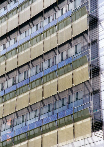
(f) Photovoltaic Power Generation System
21.1 kW solar modules are installed vertically on building balconies
facing south, and 18kW modules on building roof tops. This system generates
about 28,500kWh a year, which is equivalent to annual power comsumption
of 10 families.
(g) Ice storage HVAC system
TEPCO supplied 58.65GW as a peak load in 1995. On the peak day, over
a third of this peak demand consisted of the load for air conditioning
systems. The minimum demand at night was 40% of the peak load. As
this gap increased, the load factor decreased to approximately 55%.
Large scale buildings in Japan are characterized by footings composed of
small spaces which have double floor structures to make buildings resistant
to earthquakes. Sections from these spaces can be inexpensively converted
into thermal storage tanks. However, these spaces are not large enough
for chilled water storage tanks in this center. So, we have used an ice-on-coil
type ice storage system that we have studied for more than a decade.
The system here consists of two brine chillers (three in future), an ice
storage tank of 680m3 and ice making heat exchangers with a
total length of 26,957m (40,435m in future).
(h) Low-temperature Cold-air Air Conditioning System
A cold air distribution system has been developed for effective usage of
the ice storage system. Chilled water prepared by the ice storage
system can produce cold air approximately 10 degree centigrade, which is
6 degree centigrade lower than conventional systems. As cold air
has a heavy density and supplied air volume is reduced in this system,
the air outlet needs high diffusibility. TEPCO has developed a diffusing
system which uses a kind of circular movement. As air volume is reduced,
the size of the air ducts and the capacity of the blowers can be decreased.
This achieves energy saving.
Conventional difuser Newly developed type
 
(i) Other energy technologies adopted in the building
-
Fuel cell power generation
A building operation working group has also been established for targeted
energy operation management. As a result of all these measures, the specific
annual primary energy consumption at the centre has been reduced to 1,340
MJ (372.2 kWhth)/m2 per year. This is 35% lower than a standard
building of this type.
References:
| Created: Jun 1999 | Update: 1 Dec 2001 | By: Sam C
M Hui (cmhui@hku.hk) |
|