 |

| Home | Case
Study Index |
| Created: 11 Feb 99 | Update: 1 Dec 2001 | By: Sam C M Hui (cmhui@hku.hk) | |
|
| Home | Case
Study Index |
| Created: 11 Feb 99 | Update: 1 Dec 2001 | By: Sam C M Hui (cmhui@hku.hk) | |
| 1. Project Description | ||||||||||||||||||||||||
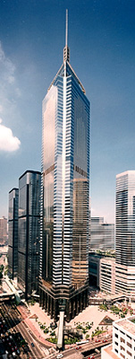
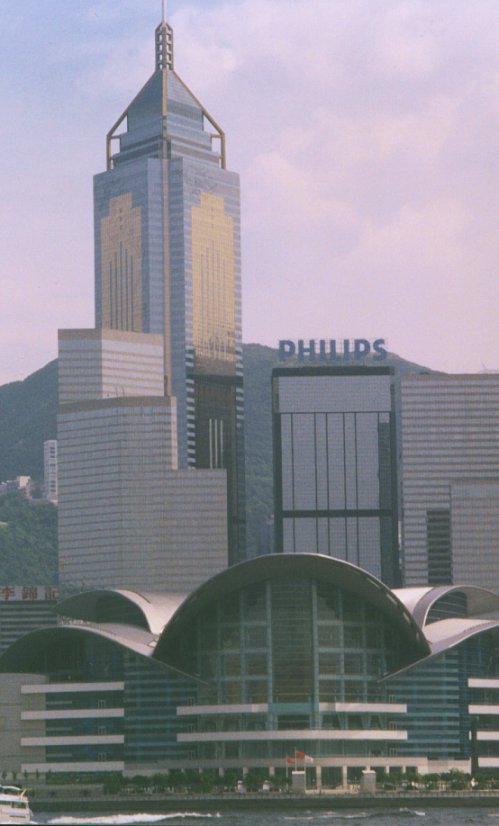
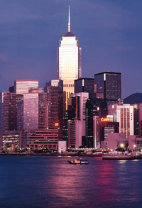
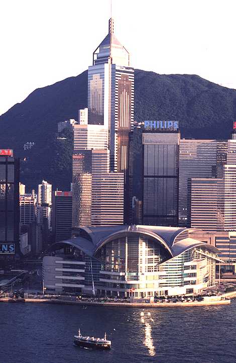
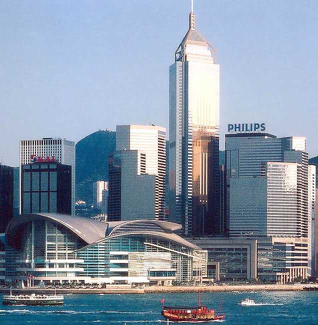
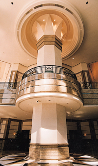
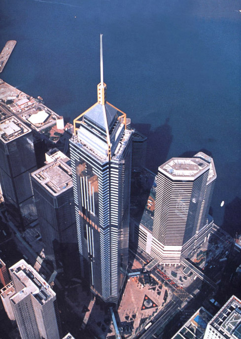
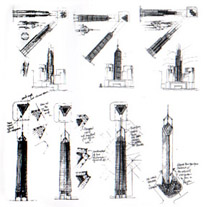
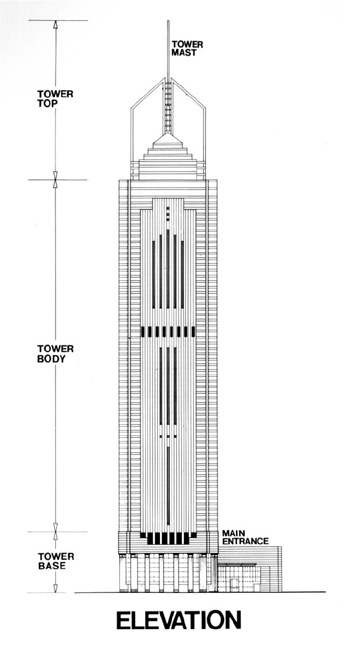
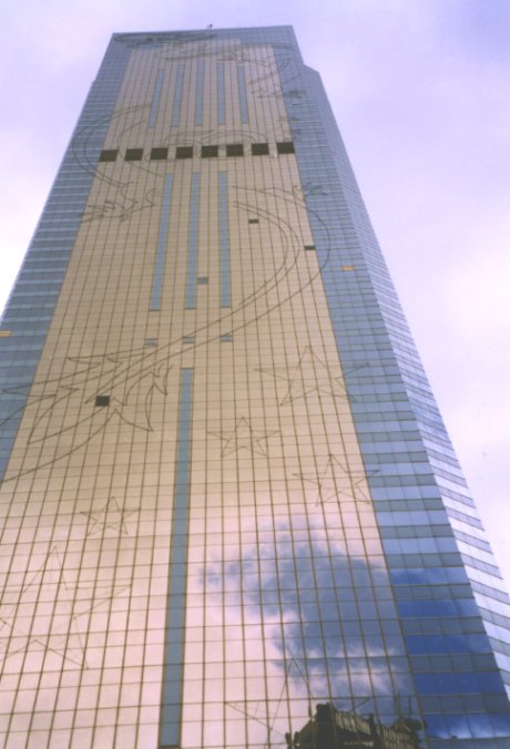
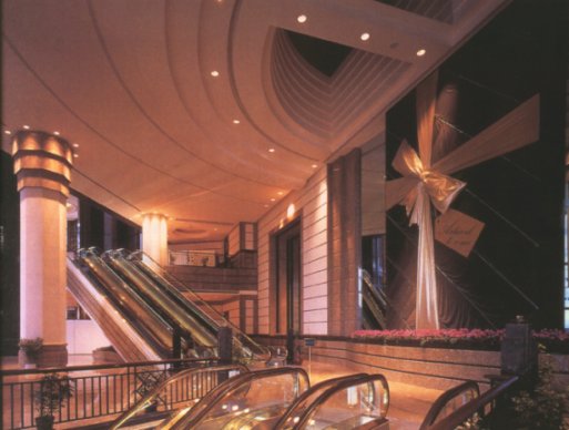
Overall view |
1.1 Developers and Project Team
|
|||||||||||||||||||||||
|
|
|||||||||||||||||||||||
|
1.3 Basic Data
|
|||||||||||||||||||||||
Overview:
|
|
|||||||||||||||||||||||
| 2. Design Constraints to Building Services Design | ||||||||||||||||||||||||
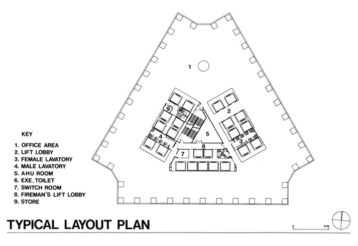
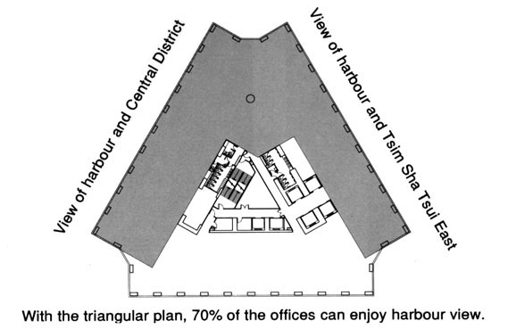
Typical Floor Plan
|
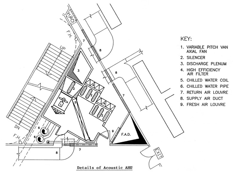
Nonetheless, the triangular building plan causes the air handling unit (AHU) room in the internal core also assuming a triangular configuration and has only limited space. This makes the adoption of a standard AHU becomes not feasible. Furthermore, all air-conditioning ducting, electrical trunking and piping gathered inside the core area have to be squeezed into a very narrow and congested corridor ceiling void. 2.2 Super High-rise Building 2.3 Maximum Clear Ceiling Height |
|||||||||||||||||||||||
| 3. Structural Features | ||||||||||||||||||||||||
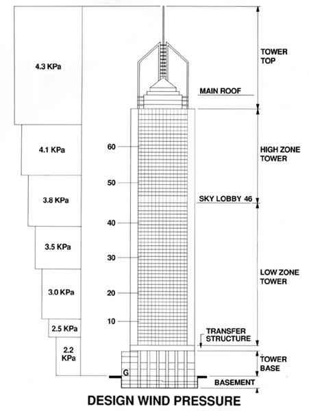
Design wind pressure |
3.1 Structural Design Constrains  (a)
The site is a newly reclaimed area with a maximum water table rises to
about 2 meters below ground level. In the original brief, a 6 storey basement
is required, therefore a diaphragm wall design came out. (a)
The site is a newly reclaimed area with a maximum water table rises to
about 2 meters below ground level. In the original brief, a 6 storey basement
is required, therefore a diaphragm wall design came out.
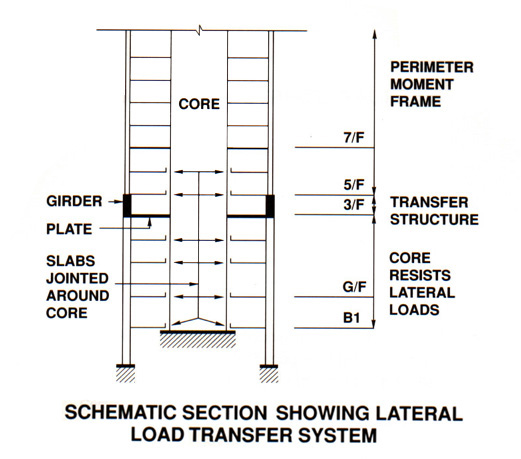
(b) The keyword to this project is: time. With a briefing in a limited detail, the structural engineer needed to start work The diaphragm wall design allowed for the basement to be constructed by the top-down method. It allows the superstructure to be constructed at the same time as the basement, thereby removing time consuming basement construction period from the critical path. (c) Wind loading is another major design criterion in Hong Kong as it is situated in an area influenced by typhoons. Not only must the structure be able to resist the loads generally and the cladding system and its fixings resist higher local loads, but the building must also perform dynamically in an acceptable manner such that predicted movements lie within acceptable standards of occupant comfort criteria. To ensure that all aspects of the building's performance in strong winds will be acceptable, a detailed wind tunnel study was carried out by Professor alan Davenport at the BLWT at UWO. For the lateral loading, the wind shear of the tower is taken out form the core at the lowest basement level, where it is transferred to the perimeter diaphragm walls. 3.2 Steel Structure Vs Reinforced Concrete
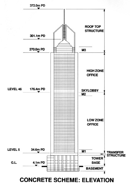
In the final scheme, columns at 4.6m centres and 1.1m deep floor edge beams were used to replace the large steel corner columns. As climbing form and table form construction method and efficient construction management are used in this project which make this reinforced concrete (R.C.) structure take no longer construction time than the steel structure. And the most attractive point is that the R.C. scheme can save HK$230 million compare to that of steel structure. Hence R.C. structure was adopted and Central Plaza is now the tallest R.C. building in the world. In this R.C. structure scheme, the core has a similar arrangement to the steel scheme and the wind shear is taken out from the core at the lowest basement level and transferred to the perimeter diaphragm walls. In order to reduce large shear reversals in the core walls in the basement, and at the top of the tower base level, the ground floor, basement levels 1 and 2 and the 5th and 6th floors, the floor slabs and beams are separated horizontally from the core walls. Another advantage of using R.C. structure is that it is more flexible to cope with changes in structural layout, sizes and height according to the site conditions by using table form system. (* The building has received a special award from the Institution of Structural Engineers in 1992.) |
| 4. Energy Features | ||
Building Envelope |
|
|
Chiller layout |
4.2 Chiller Plant Design The total cooling tonnage of the building is 5,536 TR (refrigeration tons) and the whole system was divided into three separate zones, each with its own chiller plant of approximately 1,800 TR cooling capacity. The plants are located on three multiple storey mechanical floors, namely, 5-6/F, 44-45/F, 70-72/F. With this arrangement, the system was simplified to just like three medium rise buildings with one stacked on another. One problem of such an arrangement is how to resolve the heat rejection of the chillers installed indoor on different levels, without affecting the aesthetics of the building facades. Another problem is how the building operator can efficiently operate the three scattered chiller plants. Various heat rejection proposals such as seawater cooled, air-cooled using radiators and air cooled condensers were compared. After careful analysis and evaluation, the first two schemes were dropped owing to technical constraints, time limitations and economic considerations. The direct air-cooled package chillers proposal was finally adopted, which is a flexible and cost effective scheme for the project. Aesthetical considerations required all chillers to be installed indoor. For proper heat rejection, particular arrangements were made to separate each mechanical floor into two levels. The chillers are placed on the lower level while the upper level is used as a common discharge plenum for the hot condenser air. Thus, no discharge ductings for the condenser fans connecting to outdoors are required. Condenser fans are changed from normal propeller type to vane axial type to overcome the extra pressure loss introduced by intake and discharge louvres as well as silencers. At no wind condition the air will intake from the lower level and discharge freely on all three directions on the upper level. When wind is blowing, positive wind pressure will be exerted at windward side, while negative wind pressure or suction will be exerted n leeward side. When the differential wind pressure gradually increases, up to a certain value, the hot air discharge by the chiller will be directed by the wind and blown out through the leeward side of the building. In order to efficiently remote monitor, control and operate the three independent chiller plants, an intelligent direct digital control (DDC) building automation system was employed and the central control room is located at 6th floor Engineer's Office and 1B/F Management Office. |
|
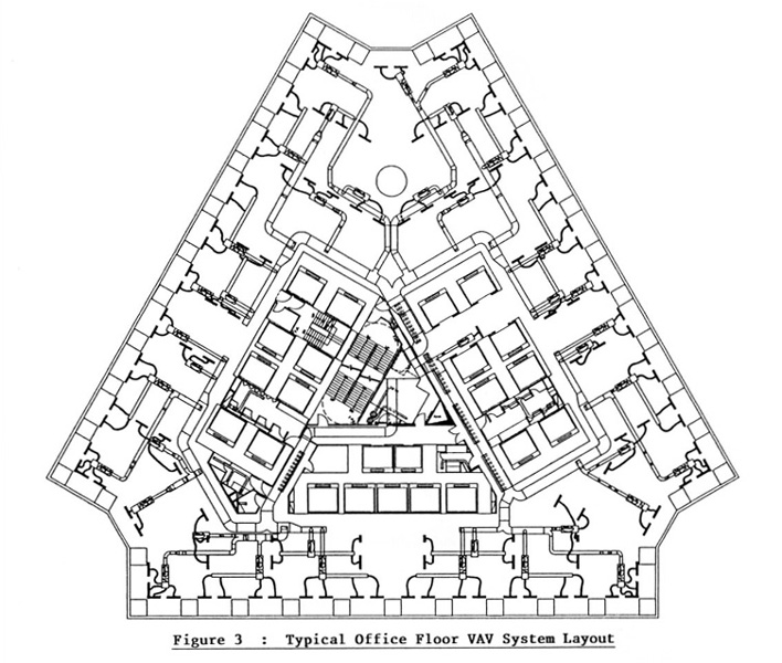
Typical floor VAV system |
4.3 Air-conditioning System
For better air quality and zone independent temperature control, all-air single duct with perimeter zone reheat VAV (variable air volume) system incorporating high efficiency air filters was used. During the partload operation the supply air quantity will be automatically regulated to suit each individual zone's cooling or heating requirements. Hence, fan power and the corresponding energy supply are reduced. Meanwhile, since the air handling units and water pipes are way from the office area and air is ducted to the occupied space, quieter operation of the system can be achieved. Routine maintenance can be carried out in the AHU room with minimum disturbance to the tenants. Various VAV systems and fan coil system for the typical office floor were compacted in the preliminary design stage. The results show that:
|
|
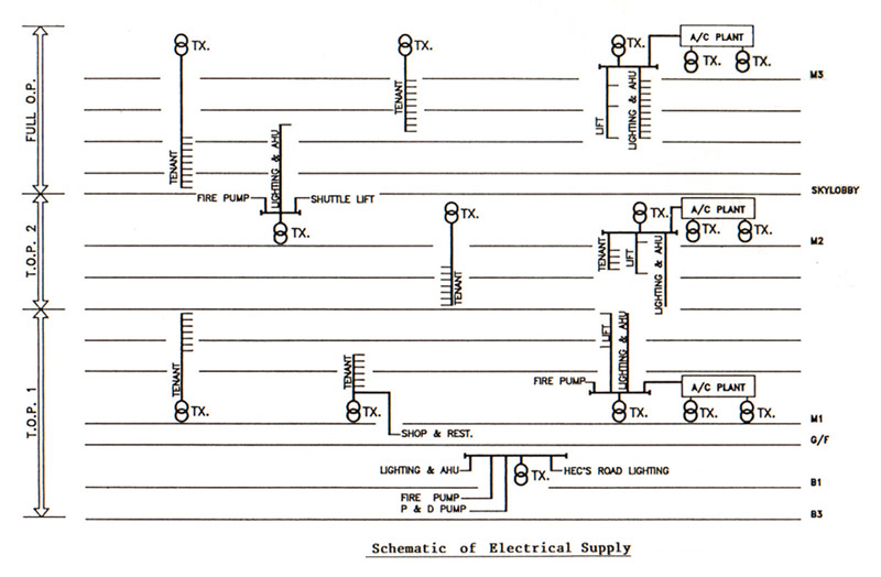
Simplified electric scheme |
 4.4
Electrical Power Supply 4.4
Electrical Power Supply Based on the areas and usages of the building, the total electricity loading of the building was estimated to be 24,000 kVA. The high rise geometric nature of the building design makes the siting of substations for general power supply and generators for essential supply an important issue. As the vertical span of the building is 292 metres above ground, significant energy loss in the power distribution system will result, should traditional centralised substation arrangement be used. The major load centres inside the building are air-conditioning plants which are located on M1/F, M2/F and M3/F. To locate the power distribution substations close to the load centres, the power company's substations were situated in 5/F, 44/F and 70/F. However, these upper floor substations created a problem in providing transportation and maintenance access to the transformers. The solution is to employ 500 kVA single phase transformers which can be wired in star connection to form 1,500 kVA three phase transformers. Since the physical size of a 500 kVA single phase transformer is very much smaller than that of an 1,500 kVA three phase one, the single phase transformer can be delivered from ground floor to the upper floors by a service lift. The aim of the lighting system is to achieve maximum output and quality of illumination with least energy consumption. The building was provided with an efficient, high quality lighting system to minimise both the energy consumption by the fixtures and the air-conditioning system which tends to remove the heat gain given off by those fixtures. In order to cope with the need in developing a modern office environment, the lighting system is also suitable for an automatic or computerised office. The standard fitting for the office area is a 600 x 1,200 mm light box with parabolic louvre reflector and 36 Watt fluorescent lamps producing an average illumination level of 500 lux at a wattage density of about 15 W/m2. 4.6 Building Management System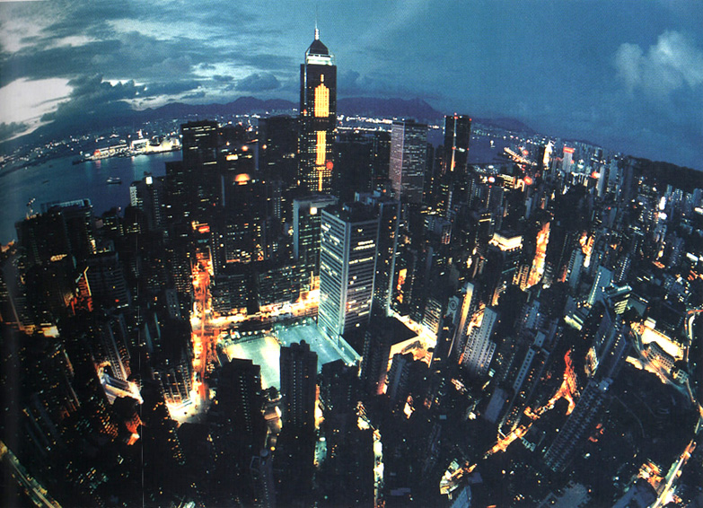 The
building management system (BMS) is the METASYS series supplied
by Johnson Controls. There are 2 central control stations located
in B1/F Management Office and 6/F Engineer Office. The system
is able perform the following functions: The
building management system (BMS) is the METASYS series supplied
by Johnson Controls. There are 2 central control stations located
in B1/F Management Office and 6/F Engineer Office. The system
is able perform the following functions:
|
|
|
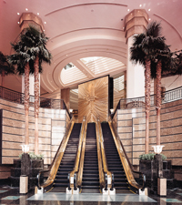
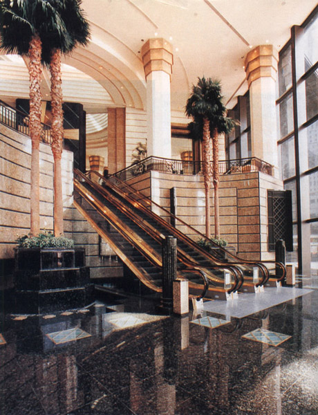
Lifts and escalators
|
4.7 Lifts and EscalatorsThe design and space requirements for the lifts serving the office tower have a major impact on the usable space on the floors and the core design. By carrying out a lift traffic analysis, a design criteria was set for the anticipated population in the building. This assumption set for population criteria is one of the most important steps that has to be made in the whole lift study. Any variation in this assumption after the fixing the core design will ruin the previous lift study or in the worse case, additional lifts might be required which again may affect the completed core design. After a field survey, a population density of 11.15 m2 usable floor area per person was suggested and the total population of about 8,700 was calculated.Based on the above population and the design criteria of 35 to 40 seconds average interval between lifts leaving the main lobby and 5 minutes handling capacity of 12% of total population, seven lift zones with four lifts per zone were required. However, because of the inherent constraint of the triangular core, it was not possible to accommodate all the 28 passenger lifts and two service/fireman lifts all the way up from the main lobby on second floor to their destination with reasonable usable floor area efficiency. To improve this, reducing the number of lifts shafts originated from the main lobby was worth considering. Sky lobby concept would be the solution.
With the adoption of sky lobby concept, seven lifts shafts are saved all the way from the main lobby on second floor to 46/F. This substantially improves the efficiency of the building by adding 80 m2 more usable floor area to each low zone floor. At a capital value of HK$5,000 per ft2, the developer would mean a gain of HK$4.3 million per floor. So, the proposal for having the sky lobby is easily justified. As a result of this arrangement, the overall efficiency of the building is over 81% for a single tenant. |
|
| 5. Other Interesting Features | ||
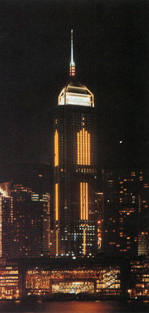
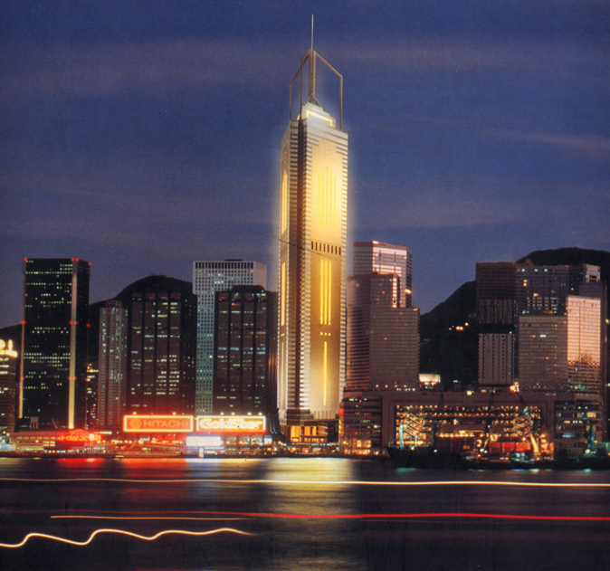
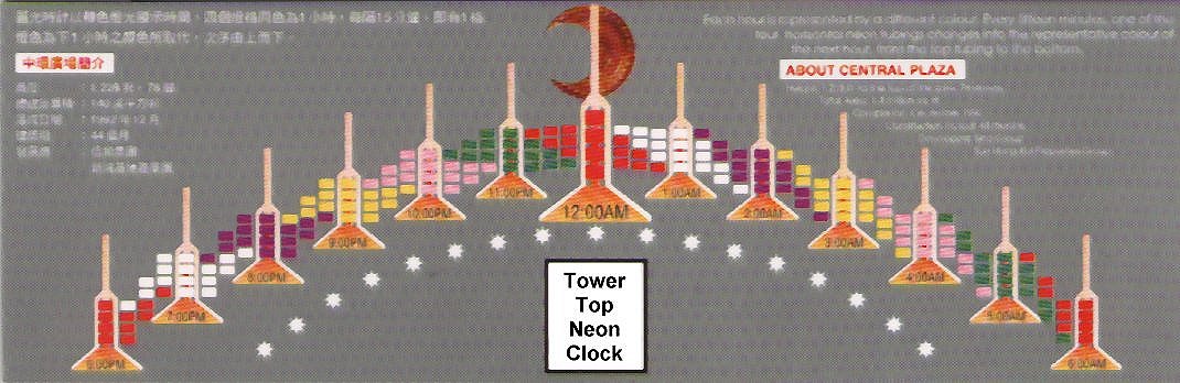
Central-neon |
neon 5.1 Neon Light Tubes(a) Neon tubings - using 1,000 neon transformers totalling 6,000 m to create a glittering image of the facade. [see demonstration here](b) By installing neon tubes on the tower top, the building can signal the time through the changing colours of the 4 sets of neon tubes. Each hour is represented by a different colour. Every fifteen minutes, one of the four horizontal neon tubings changes into the representative colour of the next hour, from the top tubing to the bottom. The time signals are sent to Central Plaza by Hong Kong Observatory. [see demonstration here] |
|
| | Home | Case Study Index | |


 2.1 Triangular
Shape Floor Plan
2.1 Triangular
Shape Floor Plan 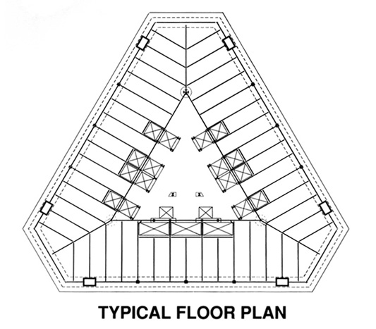


