The new and old towers are linked for users at each floor. This aspect of the design fixed the floor-to-floor height of the new building to that of the existing one - relatively low at 3.325m. To achieve an acceptable floor-to-ceiling height the services and the structure were integrated as described in the panel below.
The architectural concept was to separate the tower from the low buildings by having its floors span over the large entrance hall void and cantilever out at either end. However, the spans were too great for ordinary reinforced concrete beams within the available depth, so the competition scheme design had the eastern half of the building supported by a vierendeel wall in steel sections; the columns on the western side were to be supported by a truss at third and fourth floors. As a result of changes to allow offices along both the facades, the vierendeel wall could not be accommodated and columns were required on both sides of the building. A truss was designed at roof level from which hanging columns would be suspended to provide the necessary intermediate support to the floors. Two reinforced concrete beams spanned between the columns along the length of the building, with the floor slab spanning between them. At tender stage, the chosen contractor offered cost savings in exchange for several design modifications, which allowed construction to be simplified. Prestressed concrete edge beams with an upstand into the voided screed meant that the floors could span the distances required without support from the truss at roof level.
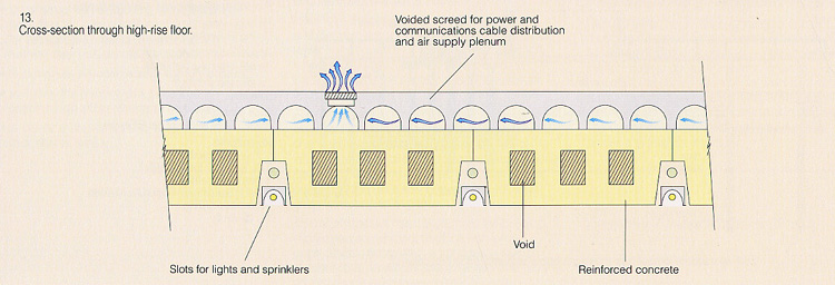
The floor system adopted integrates services and structure to minimise the depth, this gaining the maximum clear height given the horizontal constraints imposed but the existing building.
Slabs span across the building onto beams, themselves spanning between columns set in from the facade. This opens up a continuous space along the edge of the building for return air to be collected.
Lights and sprinklers are recessed into 200,, high slots between the precast hollow rib elements which are 1.8m wide between the beams.
Conduits were cast into the beams to route the services to the slots, the complexity of which was increased by the architectural requirement to achieve soffit continuity n possible corridor partition lines.
The maximum span of the slab is 9m, with a depth of 350mm chosen to minimise deflections. To reduce self-weight of the structure, voids were introduced, to be formed around prefabricaed reinforcement cages with polystyrene formers wired in place. However the contractor chose to adopt precast concrete slabs to achieve the desired effect.
The voids were generally sealed, though in some locations ducts were cast in to provide a route for the return air from the west facade. A 165mm deep, voided screed distributes the air and electrical services around the floor.
This modification
was adopted once it was clear that restrictions on service routing and
ventilation imposed by the additional upstand beam were acceptable. The
increase in edge beam depth was made at the expense of considerable
complexity, as the prestressing cables had to co-ordinate with many ducts
passing through the beam. Also, high quality control was required as the
top surface of the beam formed the finished floor level.
The architect wanted an exposed concrete finish to the columns, but to
minimise their size they were designed using steel sections encased in
concrete. A further refinement to reduce the columns' visual bulk was to
make the shape of the concrete encasement follow that of the H-shaped
steel section.
Two reinforced concrete cores give the tower stability. The south core contains three lifts, toilets, and a service riser. The south core's shape changes below the third floor as one of the car park entries had to pass through it at ground level, but this was compensated by introducing other walls to maintain stiffness and strength at this level. As the cores are relatively slender, the main air risers are outside them to avoid large holes through core walls, reducing their stiffness. Even so, wall thicknesses up to 600mm had to be adopted. Due to the shape of the building and the location of the cores, the south core carries the majority of the windloading, which was calculated according to the Frankfurt design guide for high-rise buildings. This required a dynamic analysis of the building using the program ETABS. In accordance with the design guide, amplification of the wind loading was required due to the low natural frequency of the building structure.
The Two towers are structurally independent and allowances for movement between them were required. The main elements affected were he facades, the floors, and the services at the interface.
Low building and 'Pillbox'
The relatively simple-looking low-rise building facing Charlottenstrasse and the Pillbox has hidden structural complexities. Its reinforced concrete walls at first and second floors to the facades, and forming the central corridor, are in turn supported by circular columns in the ground floor. The facade walls are cantilevered out beyond the columns. The
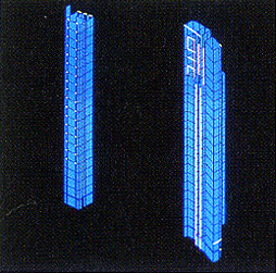
Lateral analysis model
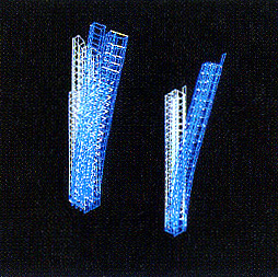
Dynamic analysis output
The Pillbox, a three-storey drum which cantilevers over the low-rise building at its eastern end, is supported only by a central reinforced concrete core, from which balanced cantilever steel beams project out to pick up hanging columns supporting the floor edges. This was necessary to create the sense of the drum 'hovering'.
Most of the vertical structure in the basement consists of reinforced concrete walls to maximise the number of parking spaces. A mechanical parking system was introduced to increase the number of spaces available, and this required the construction of a sub-basement 16m down below basement level. Diaphragm walls were used, with an intermediate slab for horizontal support.
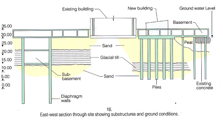
The settlement analysis that Arup carried out predicted that differential settlement along the length of the building would be less with this foundation arrangement than if the whole building was piled. The existing tower was founded on a raft beneath a single-storey basement. Due to the new basement's greater depth, dictated by external ground levels and the deeper foundation slab required, excavation extended below the existing foundations. This required underpinning.
Due to the load imposed by the new high-rise building, it was predicted that differential settlement would cause the existing building to lean towards it. A system of monitoring was installed around the latter to follow the effect of the surrounding construction on it, whilst a grout injection system was installed beneath to enable it to be raised back to vertical.
Here, as in the rest of Berlin, the groundwater level is about 3m below ground level. To construct the basement, the groundwater level was temporarily lowered by dewatering.